CG Compositing Series – 4.1 LightGroup / AOV Paradox
In this final installment of the CG Compositing Series, we focus on using LightGroups and Material AOVs together in a single workflow, and solving the paradox that come with it.
Why do these 2 rebuild methods seem to clash?
We cover the following topics in the video and in this blog post:
- The complications of splitting LightGroups per Material AOV
- A method for transferring changes between setups using a Difference Map
- The pitfalls of using Subtraction and the advantages of using Division
- A comparison of math operations: Add/Subtract vs Multiply/Divide
- A stress test of the Division-based setup
- Template layout strategies and rules to keep your rebuilds stable
- Carrying changes across the template from the 1st rebuild to the passes of the 2nd for the most interactive user experience.
- Ideas and techniques you can apply in your own CG Templates.
SlideShow PDF Download here:
What is the LightGroup / Material AOV Paradox?
Why do these two rebuild methods seem to clash?
We basically have 2 setups that are incompatible with one another, making it hard to use them at the same time.

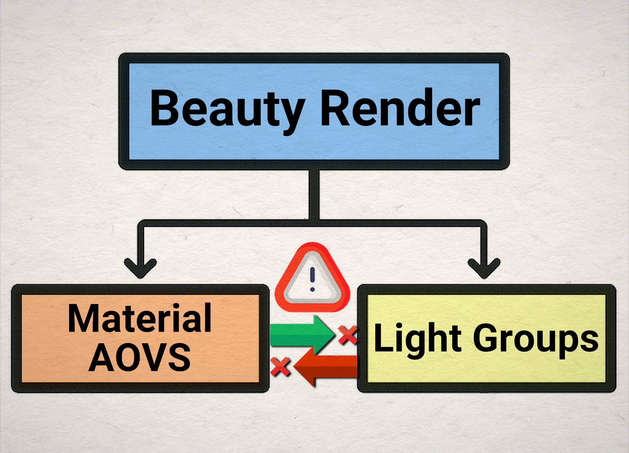

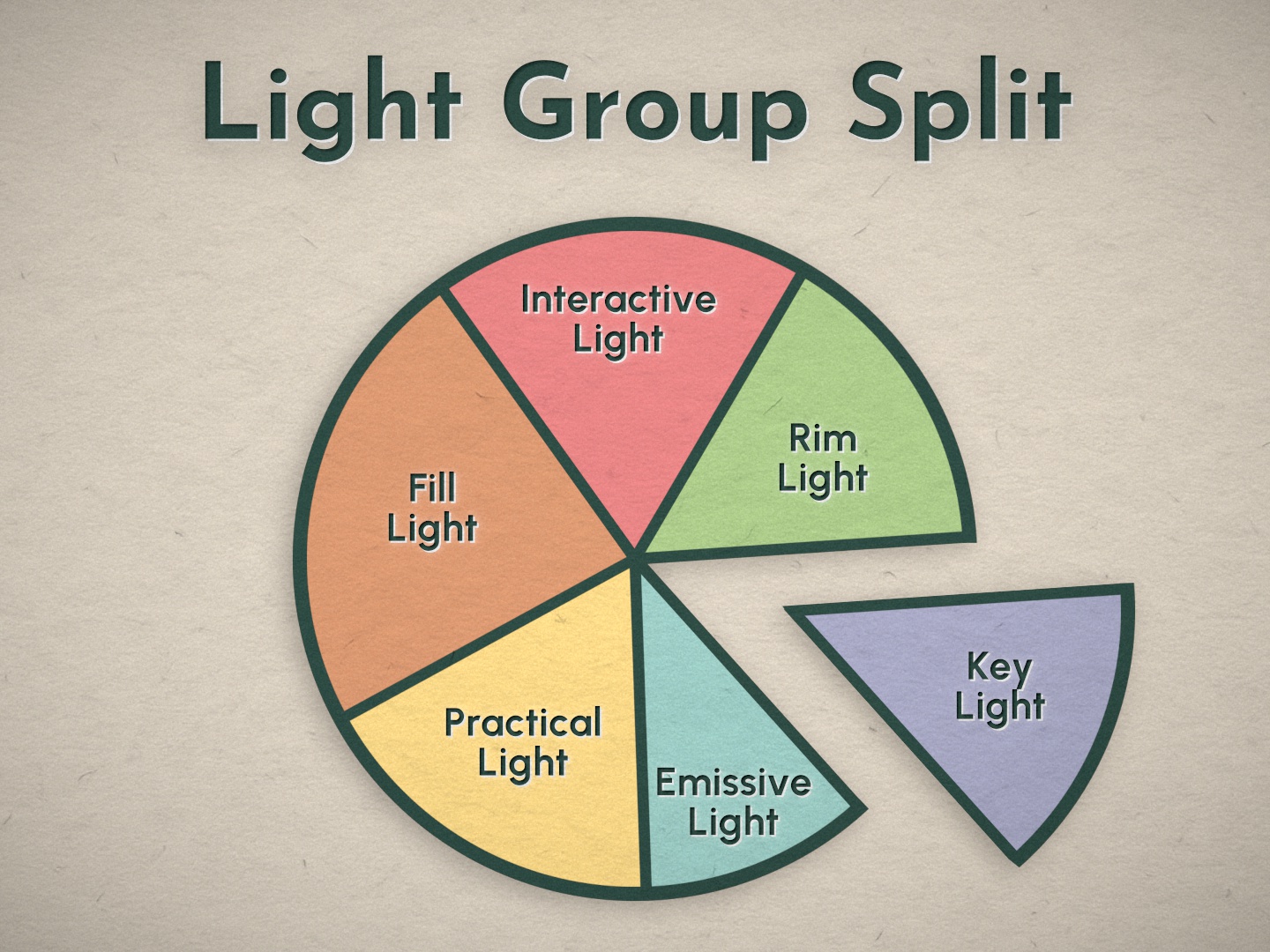
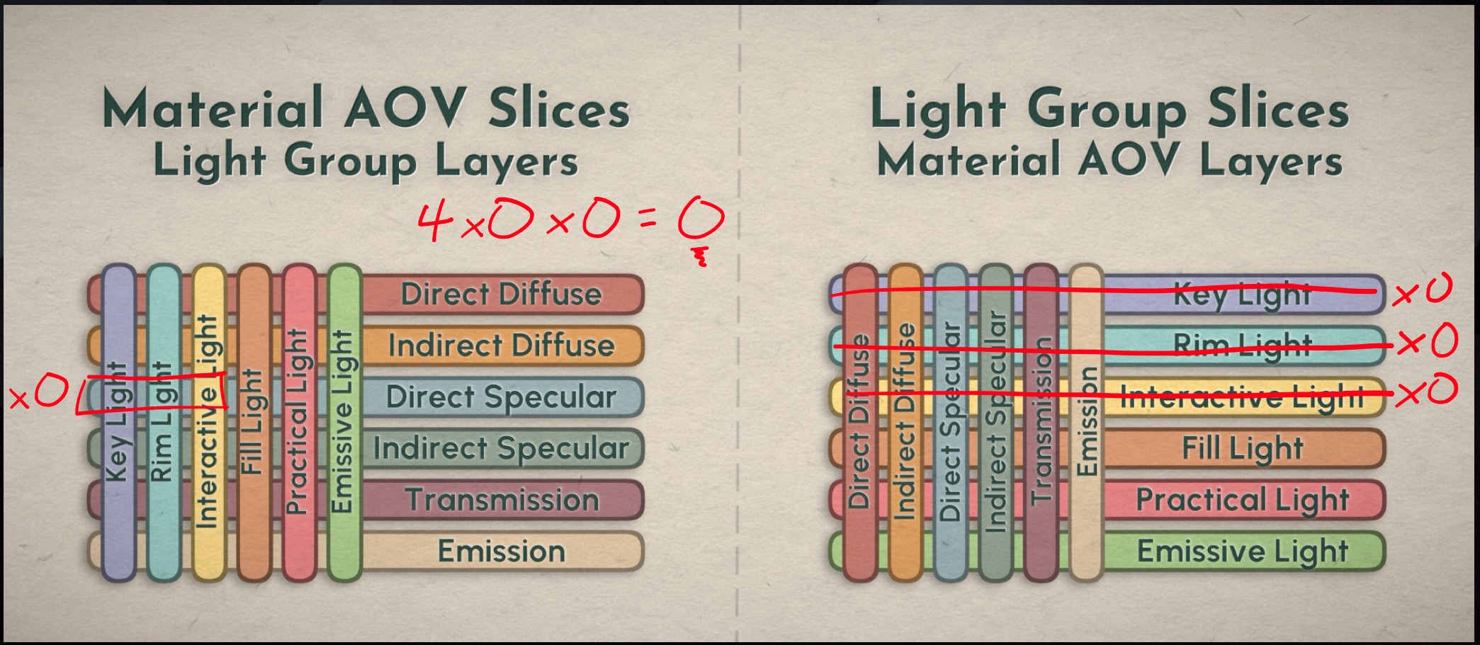
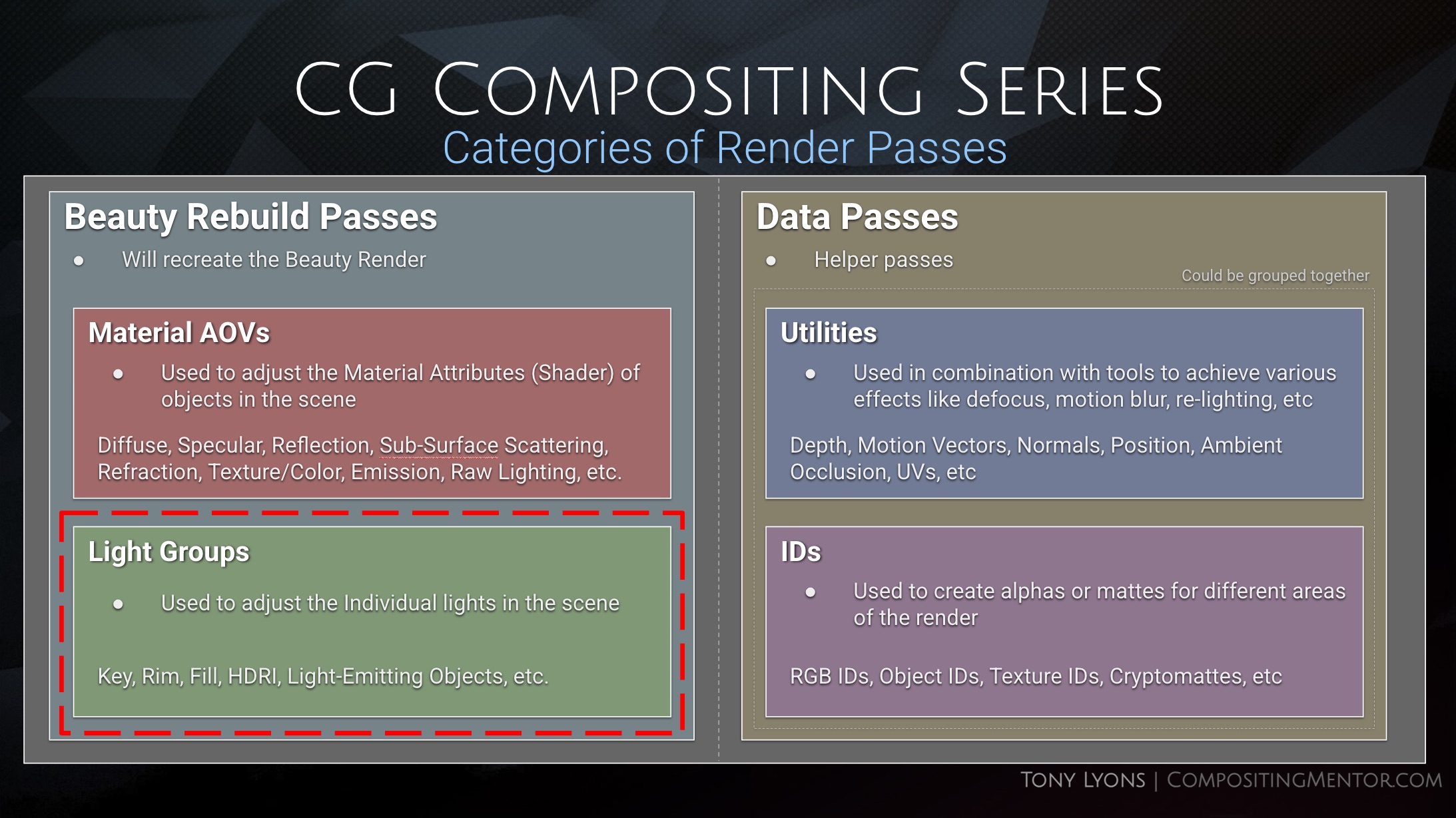
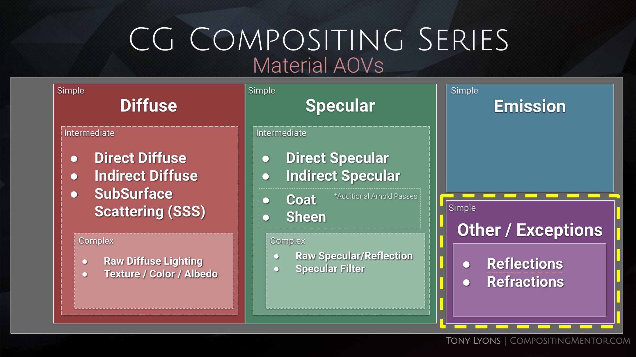
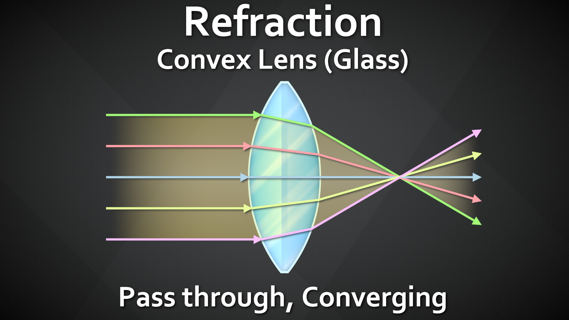
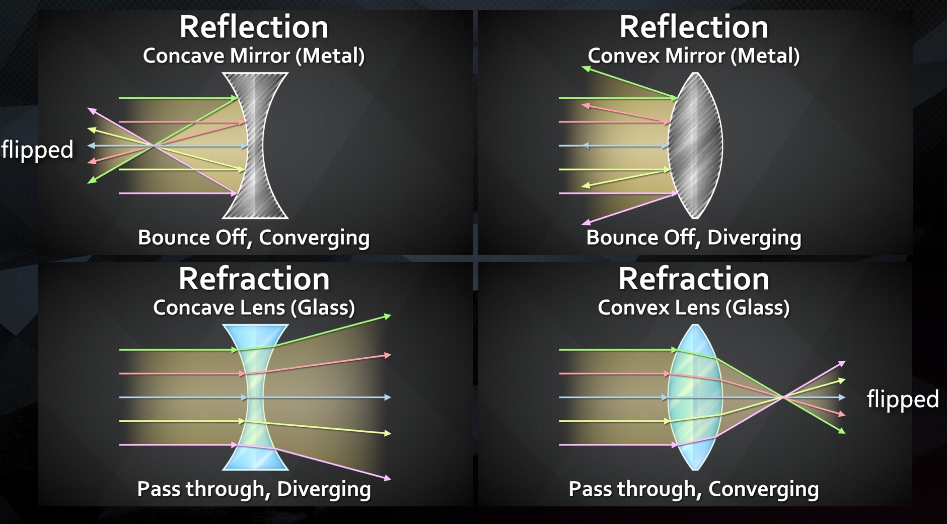
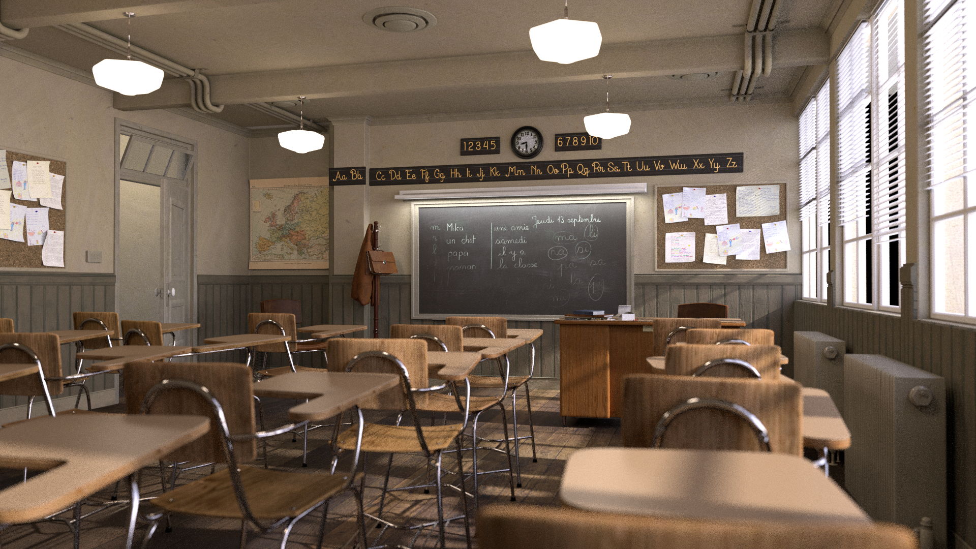
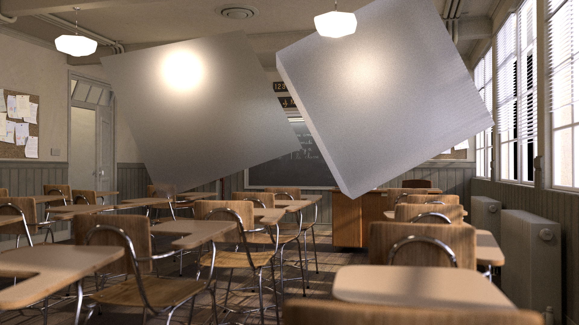
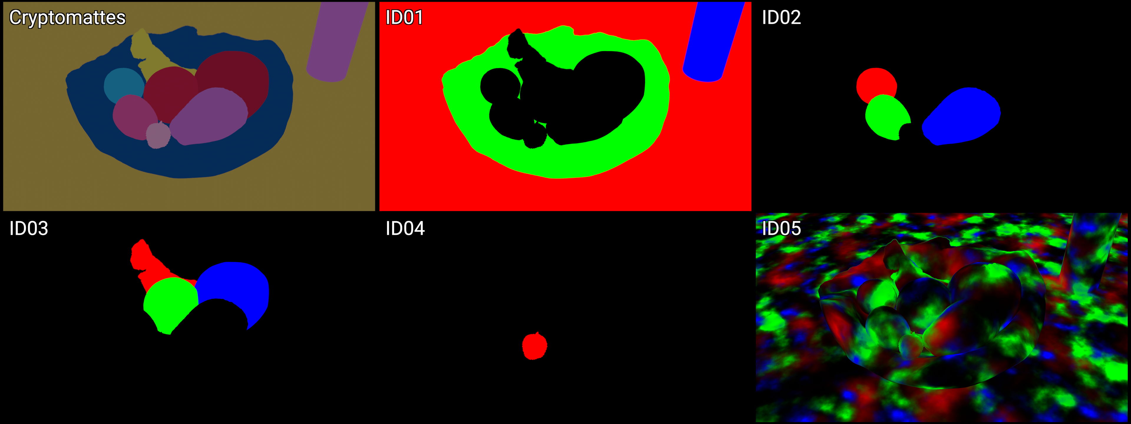
Both the Light Groups and the Material AOV Rebuilds are different ways to Slice the CG Beauty Render

But this is not the full story, for a better overview of the situation, we need to look at the same image from a slightly different angle.
The Passes of the Opposite Rebuild actually exist within each slice of the Current Rebuild
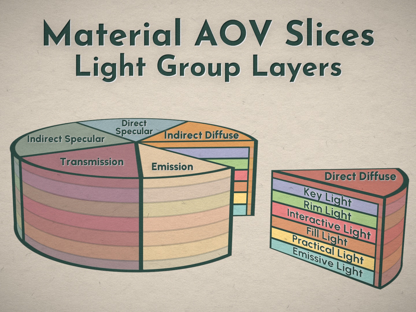

They are fully embedded and intertwined in one another.
The Paradox:
How do you make changes to both Rebuilds if the Passes are already embedded within each other?

Possible Solutions to the Paradox:
Let’s explore some possible solutions to this problem.
Split Pass Workflow: Split out Material AOVs per LightGroup
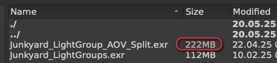
Download the larger LightGroup-per-AOV split Render here or at the bottom of this blog
Junkyard_LightGroup_AOV_Split.exr ( 223 mb )
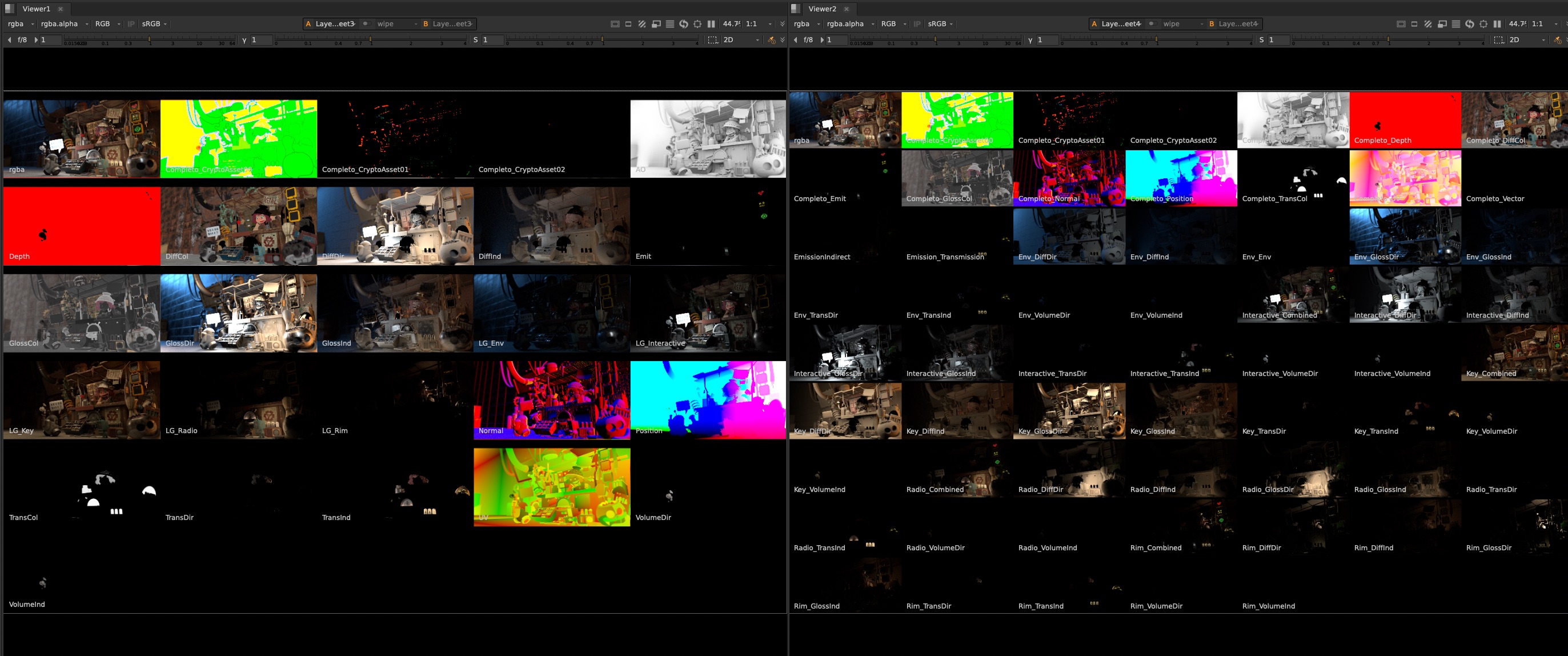
We could decide to brute force split out each pass even further, into Material AOVs per Light Group.
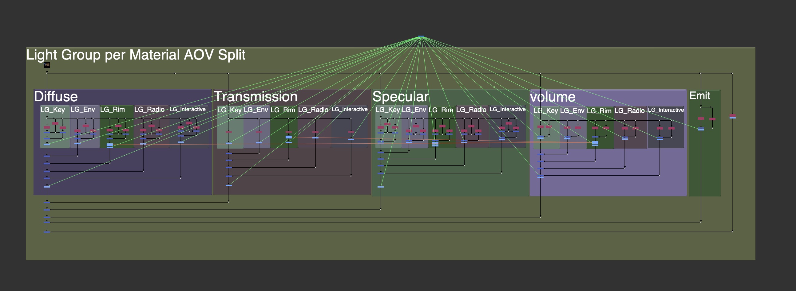
When we rebuild it you could either prioritize it as Larger buckets of Material AOVs, made up of each LightGroup.
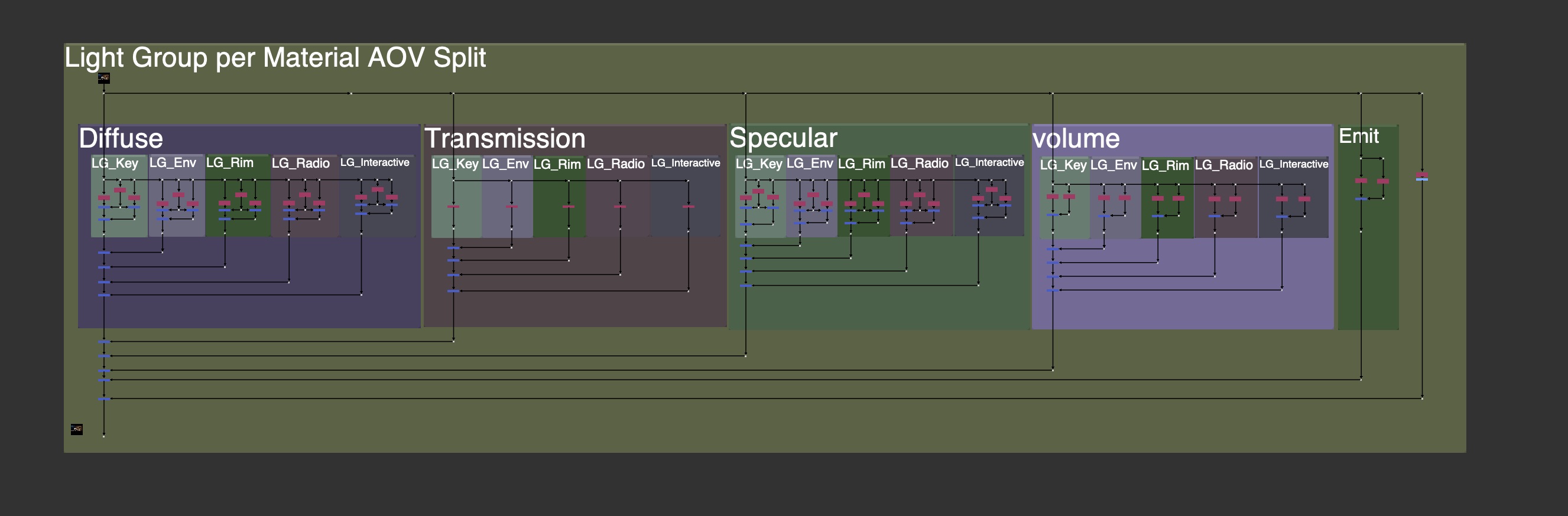
Or prioritize it as larger buckets of LightGroups, made up of each Material AOV, like a mini-Beauty Rebuild per light.
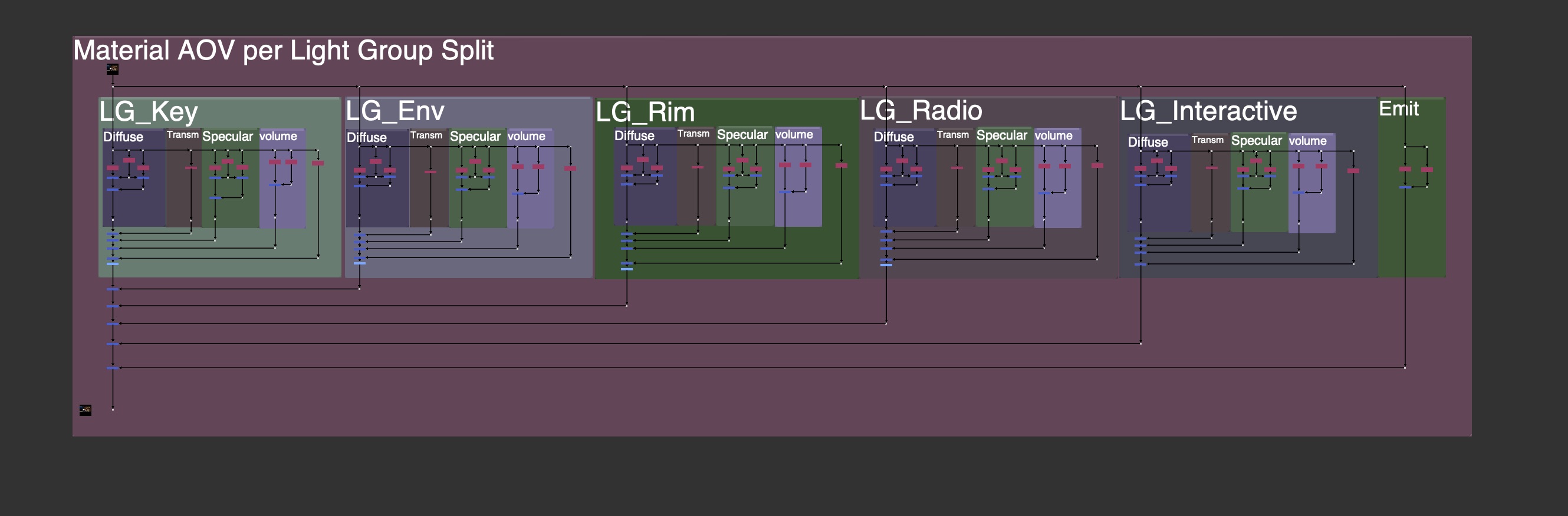
There are many problems with this workflow however:

There are many more layers and channels rendered, making file sizes larger, and nuke slower to process and more difficult to work with.

There is often a need to clone or expression link grades and color correction changes across different parts of the setup in order to affect all the lights at once, or all the material AOVs at once. Creating a clone or expression hellscape.

There are also cases where you will see a master control and expression links, so the user does not get lost in the linked/cloned nodes.
You may also see the entire setup in a Group Node, to hide it and only expose necessary controls.

Compositing is never that straight foward however and we should not be compositing from within a Group node. We often need to pull masks, rotos, elements, etc from other parts of the main node graph, and if everything is in a Group, it becomes difficult to get that information inside of the group to use.
Most Compositing should happen exposed in the main node graph to avoid any headache, and not hidden away in a Group that a user needs to jump in and out of.
This extra split workflow has many cons, let’s look at some other workflows to solve our paradox problem.
Transferring Changes from 1st Setup to the 2nd Setup
Another workflow is trying to capture and transfer the changes from the 1st Rebuild Setup to the 2nd Rebuild Setup. This is the basic idea of the workflow at its core:
An example of this technique could be illustrated from Machine Learning or Generative AI workflows, and is called Style Transfer.
In the below image, I start with an image of a bearded man. I have 2 separate models that are making changes. The first might be for facial expressions and shaves, and the second is for applying makeup. On the left side, I make a change to make the man beardless, and with an angry expression. On the right side, I’ve told it to apply clown makeup. If we want to combine the 2, I might want to package the “Beardless Angry” Changes, and apply that over to the clown makeup side. My result would be a Beardless Angry Clown.

This is a silly example but illustrates the workflow we want to use in Nuke to capture our first changes and apply them to our second changes for a combined change.
But how can we capture and package those changes from the first setup?
Subtractive (Absolute) Difference Method
- We can find the difference between the 1st Rebuild and the Beauty Render using Subtraction
- Temporarily store the changes in a subtractive difference map
- Apply the 1st changes to the 2nd Rebuild Setup

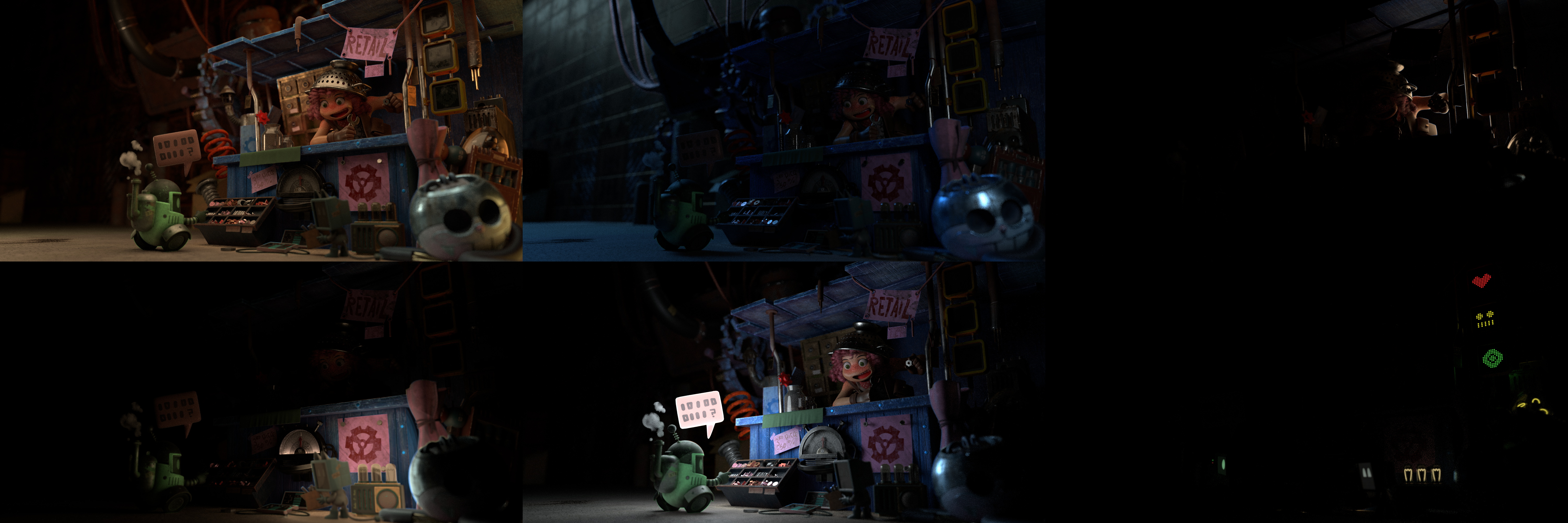
Taking one of your rebuilds, either Material AOV comp or LightGroup comp, and subtracting the original Beauty Render will give you the Subtractive Difference Map, as seen below:

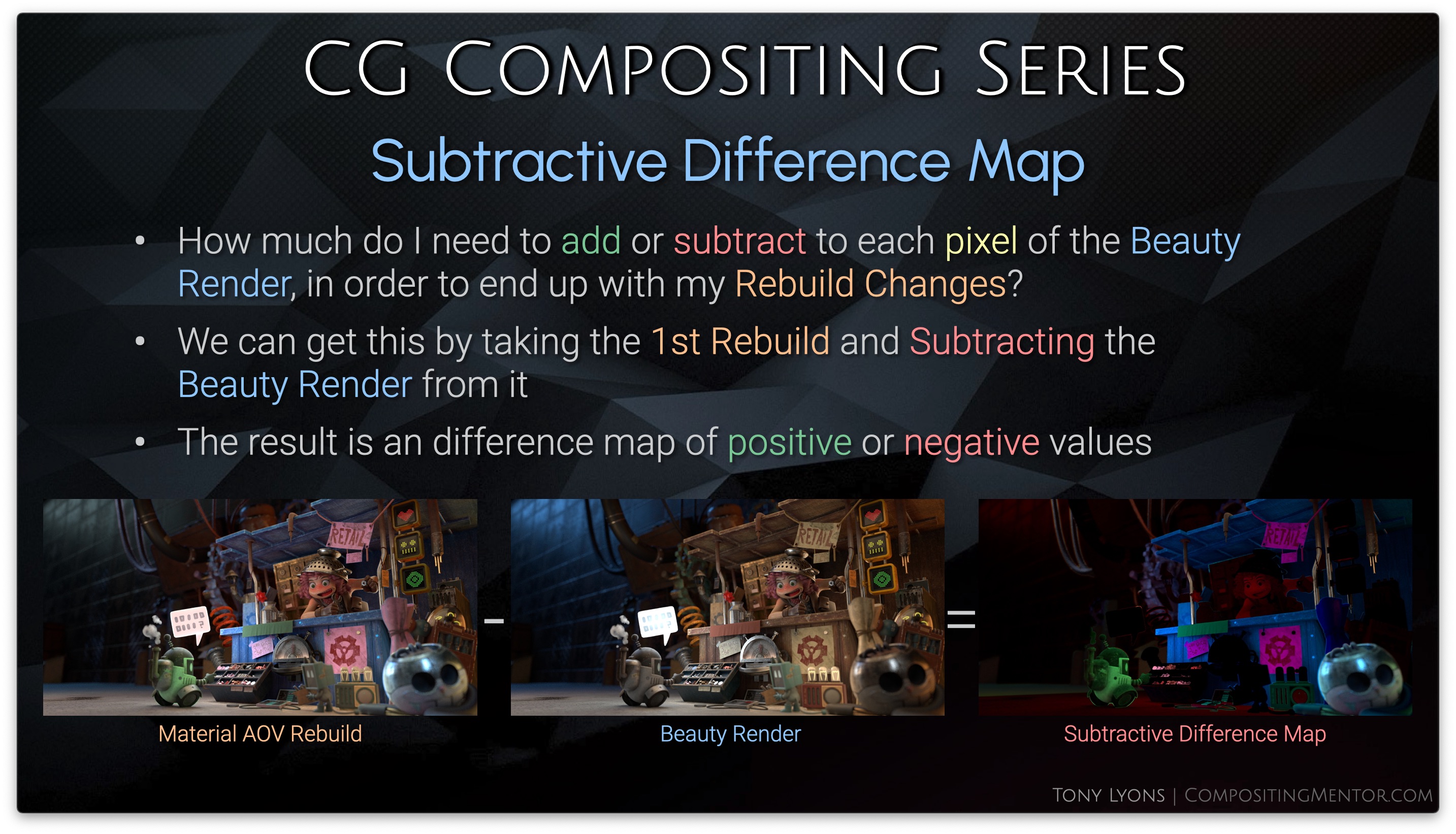
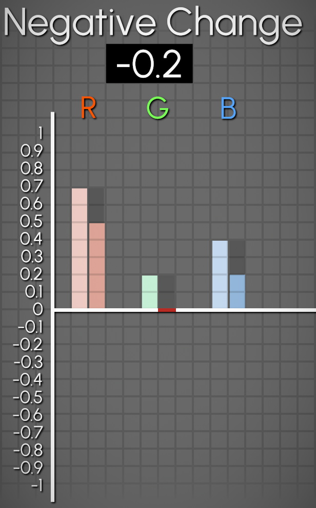
The image itself is a map of positive and negative values, telling us how much we would need to add/subtract from the Beauty Render in order to get the result of our changed Rebuild.
- Values of Zero will have No Change
- Positive Values will get Brighter
- Negative Value will get Darker

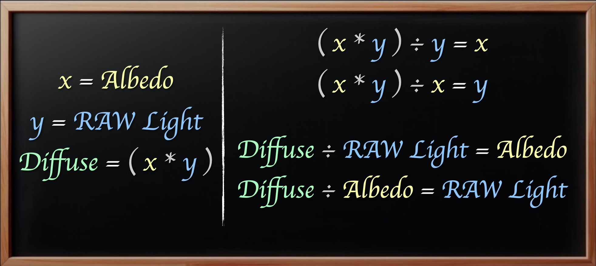
Let’s get into some equations to help us understand the math behind this workflow.
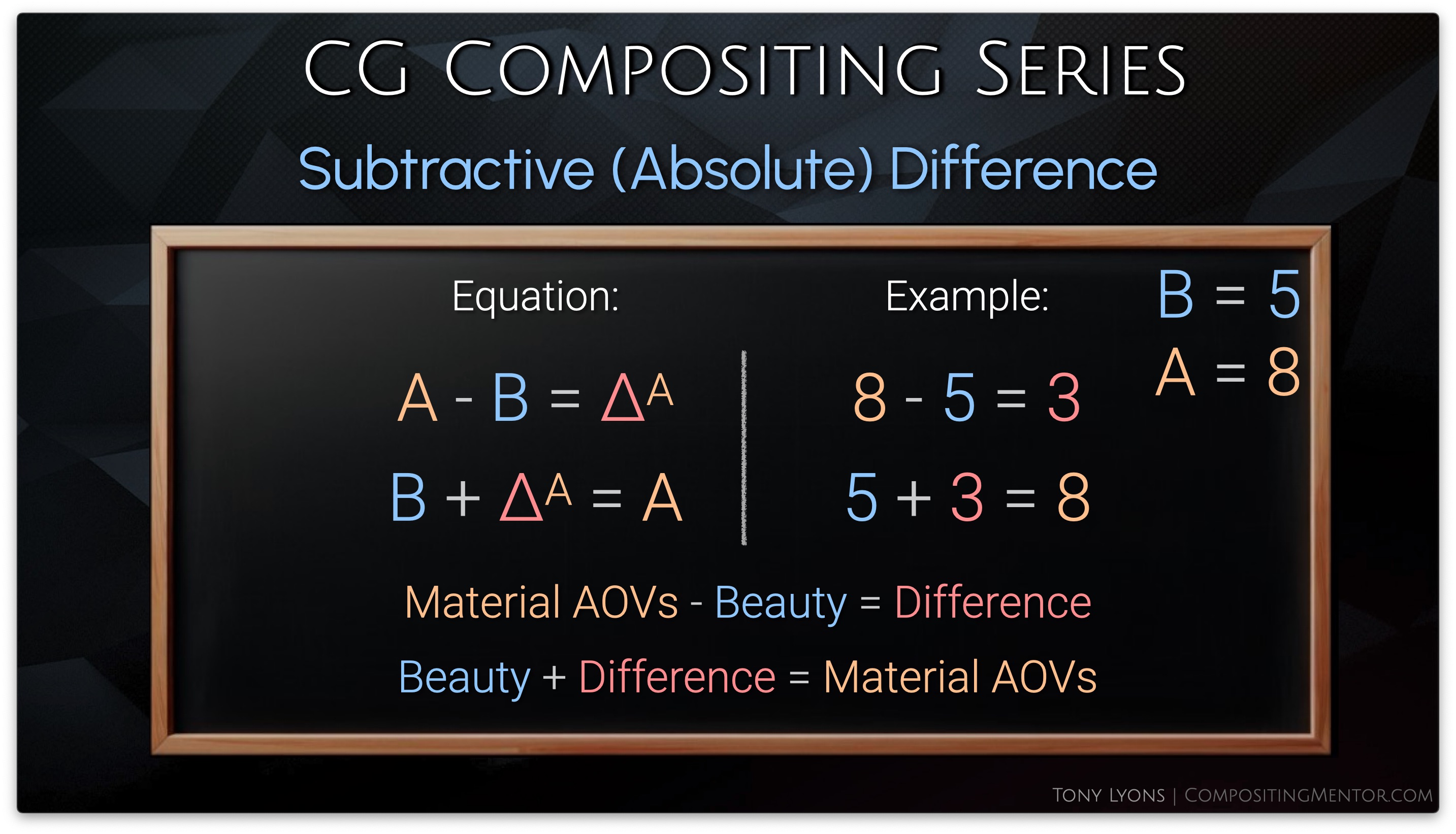
First let’s define a helpful math symbol: Delta, which stands for “The Change” or “The Difference”

First we’ll do a basic inverse operation with subtraction and addition.
Material AOVs – Beauty = Difference
Beauty + Difference = Material AOVs
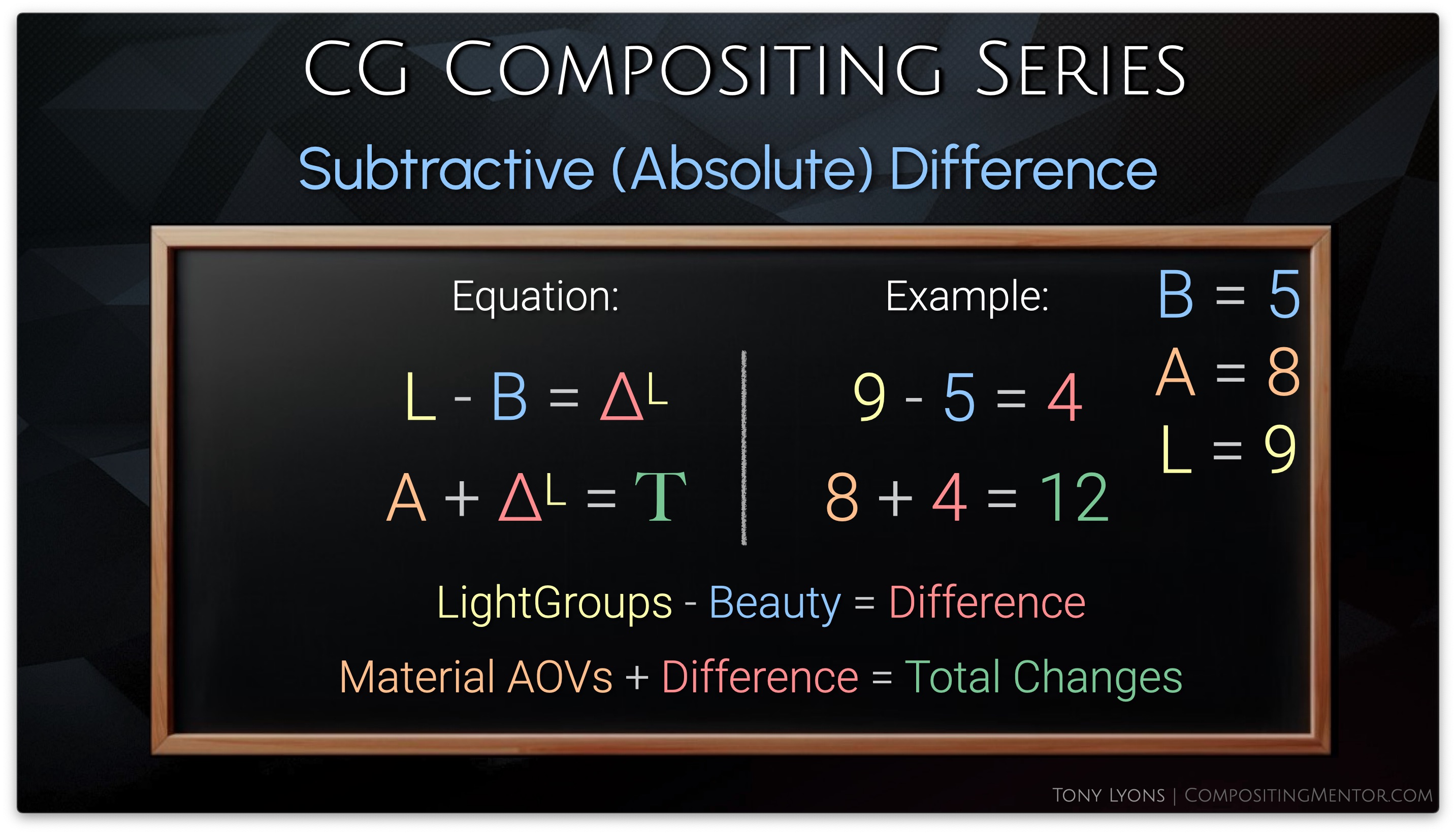
Instead of adding the difference back to the Beauty, let’s swap the Beauty out for the result of our LightGroups comp. So I am adding the difference of the Material AOVs comp onto the LightGroups comp, to hopefully get the combined changes.
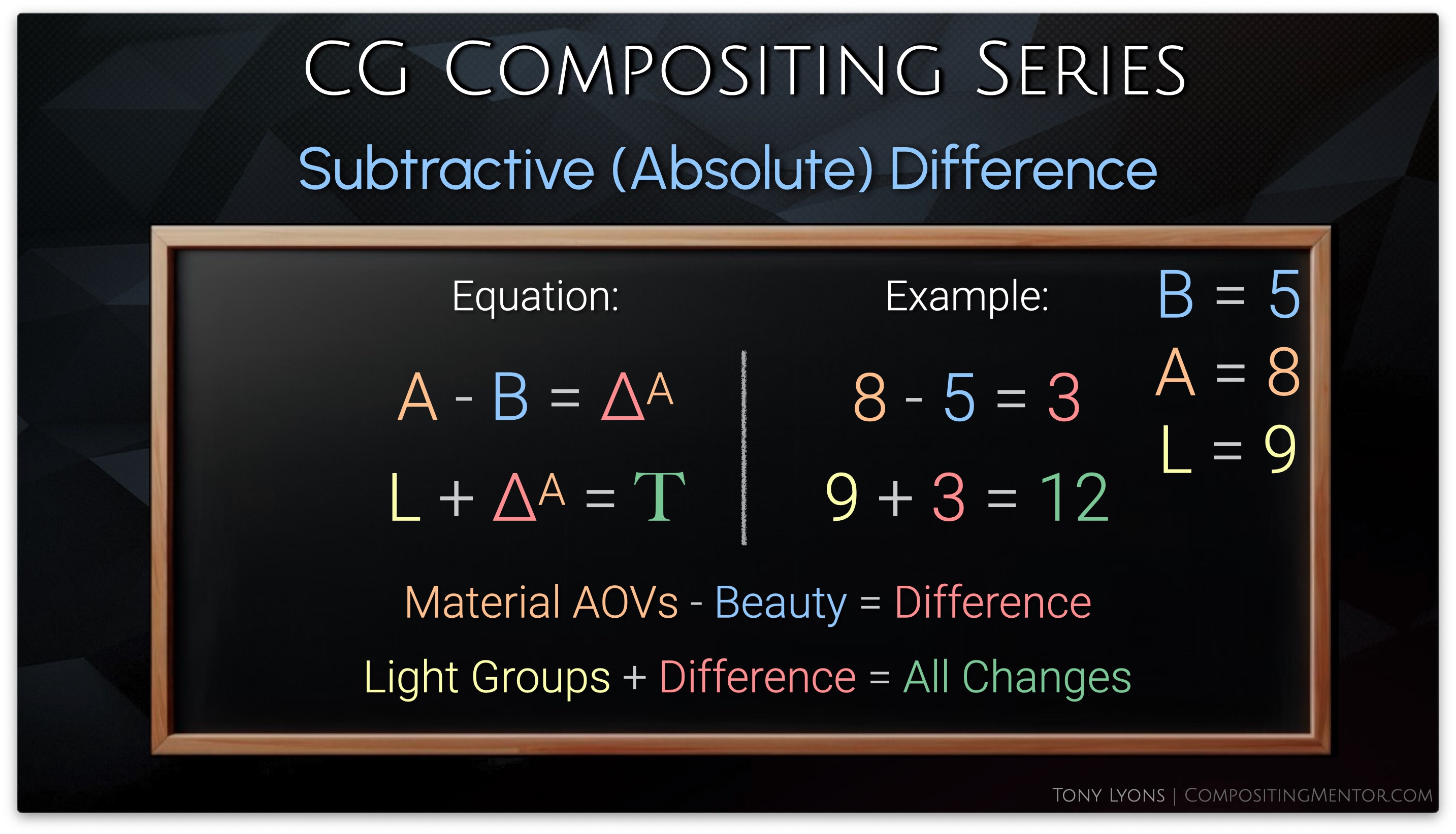
It’s important to realize that we do not need to start with the Material AOVs and transfer to the LightGroups, but we could also just as easily start with the LightGroups and transfer those changes over to the Material AOVs, it’s a matter of preference, but the result will be the same.
Let’s try this in nuke, by taking the Material AOVs output, minusing the Beauty Render, and then applying our subtractive
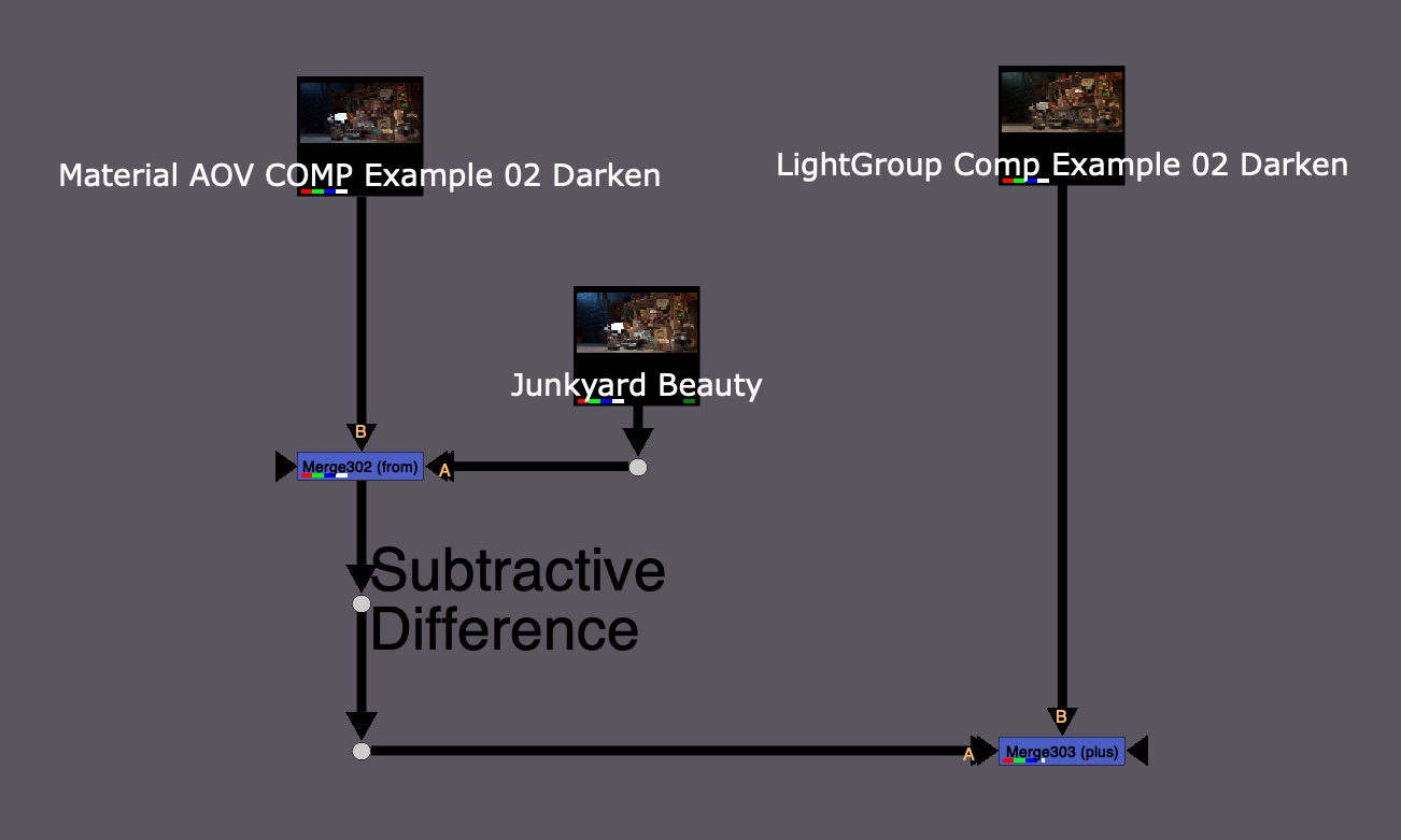
The resulting image kind of works, but is also full of problems with odd colors and seemingly black hole areas

Let’s take a look at what is going wrong with the Subtraction Difference Method.
Subtractive (Absolute) Difference Problems
- The Subtractive Difference Map represents Absolute Values
- This tells you the exact values to add/subtract to bring the Beauty Render to the Changed Rebuild
- The Subtractive Method (Absolute) only works well if you Brighten values in the Rebuilds, or only Darken them slightly
Brightening both setups will be fine, as the results will only increase.
Darkening both setups however, runs the risk of going below zero and into negative values when the change is applied to the 2nd Setup. The darker the changes on both sides, the higher the risk of negative values.


Remember that the Rebuild passes are embedded in each other’s setups. If we darken some lights, and then darken the Specular, since the specular also contains all the lights, we are essentially subtracting those light groups twice and getting negative values.

So if this Subtractive Difference Method is giving us issues, let’s look at any other ways to get the difference map.
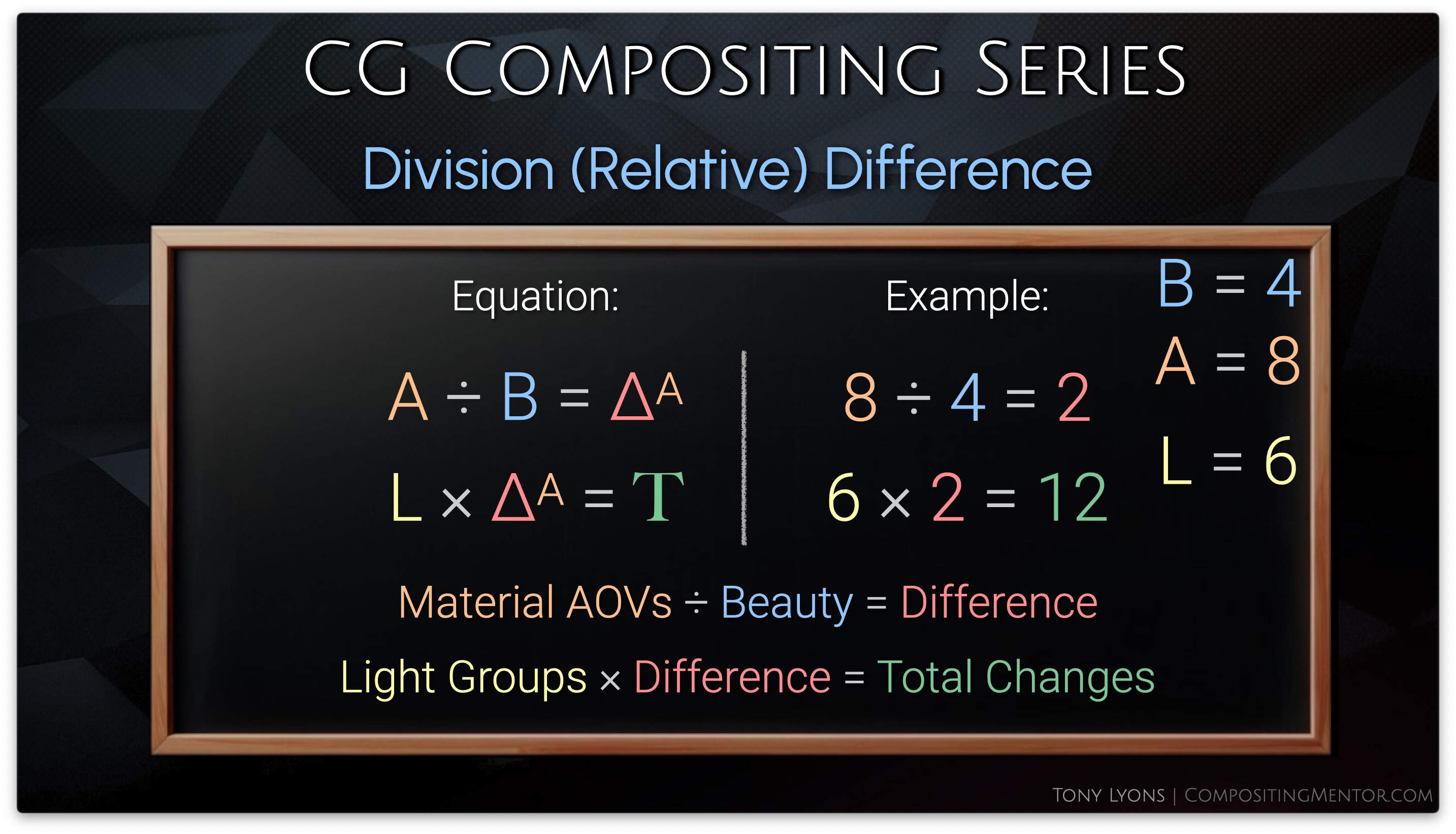
Division (Relative) Difference Method
Let’s ask ourselves: How can I go from 8 to 4?

Obviously we could subtract 4, and 8 – 4 = 4
But if we had a new, lower number, such as 2, and we also minused 4, we’d get -2.

We could also divide 8 by 2, therefore halving it, and we’d also arrive at 4.
Then trying to divide 2 by 2 will get us 1, it is also halved.
The number of change from 8 was -4 but from 2 it was only -1. This number of change is Relative to the input number. It is a ratio or a percent of what the start number is, so it adapts to our input.

Of course, this could also be represented as multiplication. divide by 2 is the same as multiply by 0.5

So instead of trying subtraction and addition, let’s now try divide and multiply
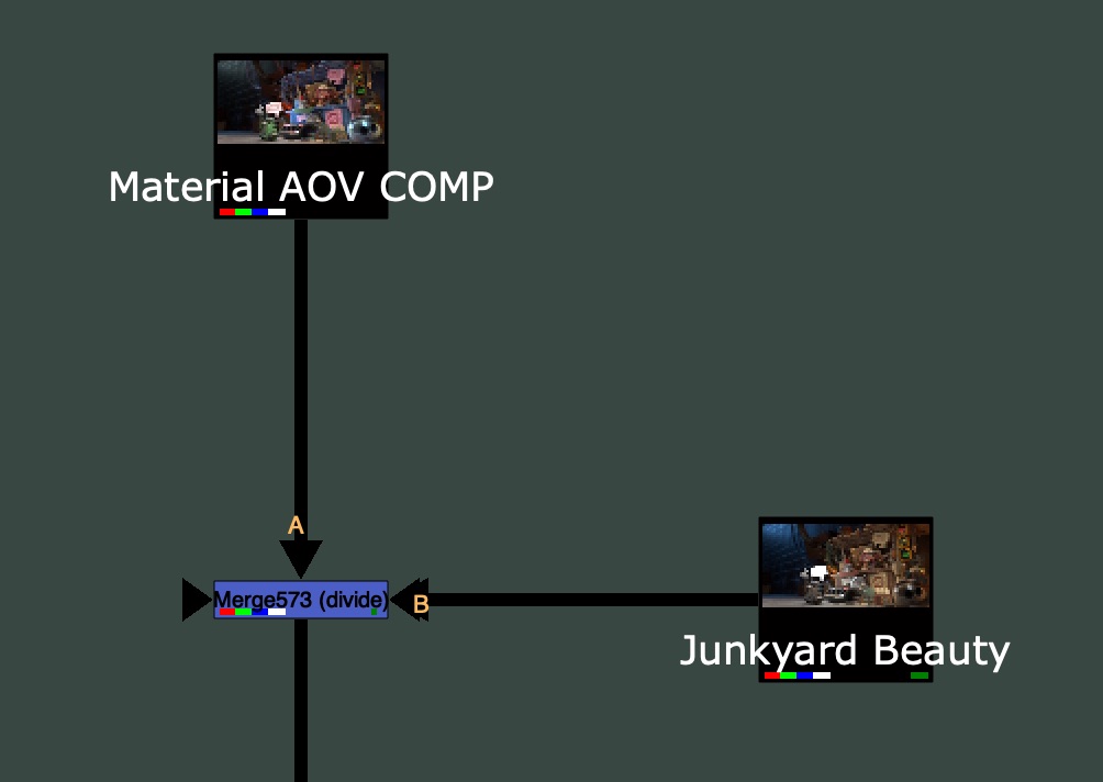
The Result is a Division Difference Map that looks a lot different than our Subtraction Difference Map
Now let’s multiply this with our 2nd Rebuild, the LightGroups side:

Side Note: Since Nuke’s Merge node does not have a native B / A operation, if you ever wanted to swap the A and B inputs and have the disable default to the Rebuild instead of the Beauty (for Templating reasons), then you would need a special MergeDivide.

Feel free to download this tool here: MergeDivide.nk
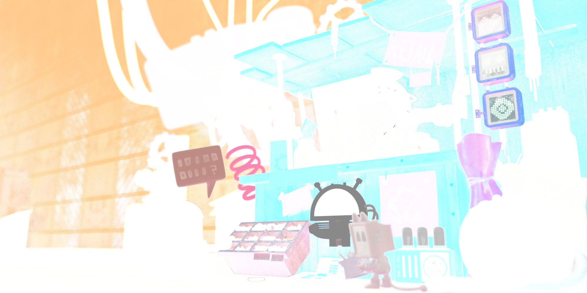
The Result from applying the Division Difference below looks a lot better than the Subtraction Method, and there are no longer any Negative Values in the image.

So why does this suddenly work? And what is going on with that Division Difference Map?
Division (Relative) Difference Map
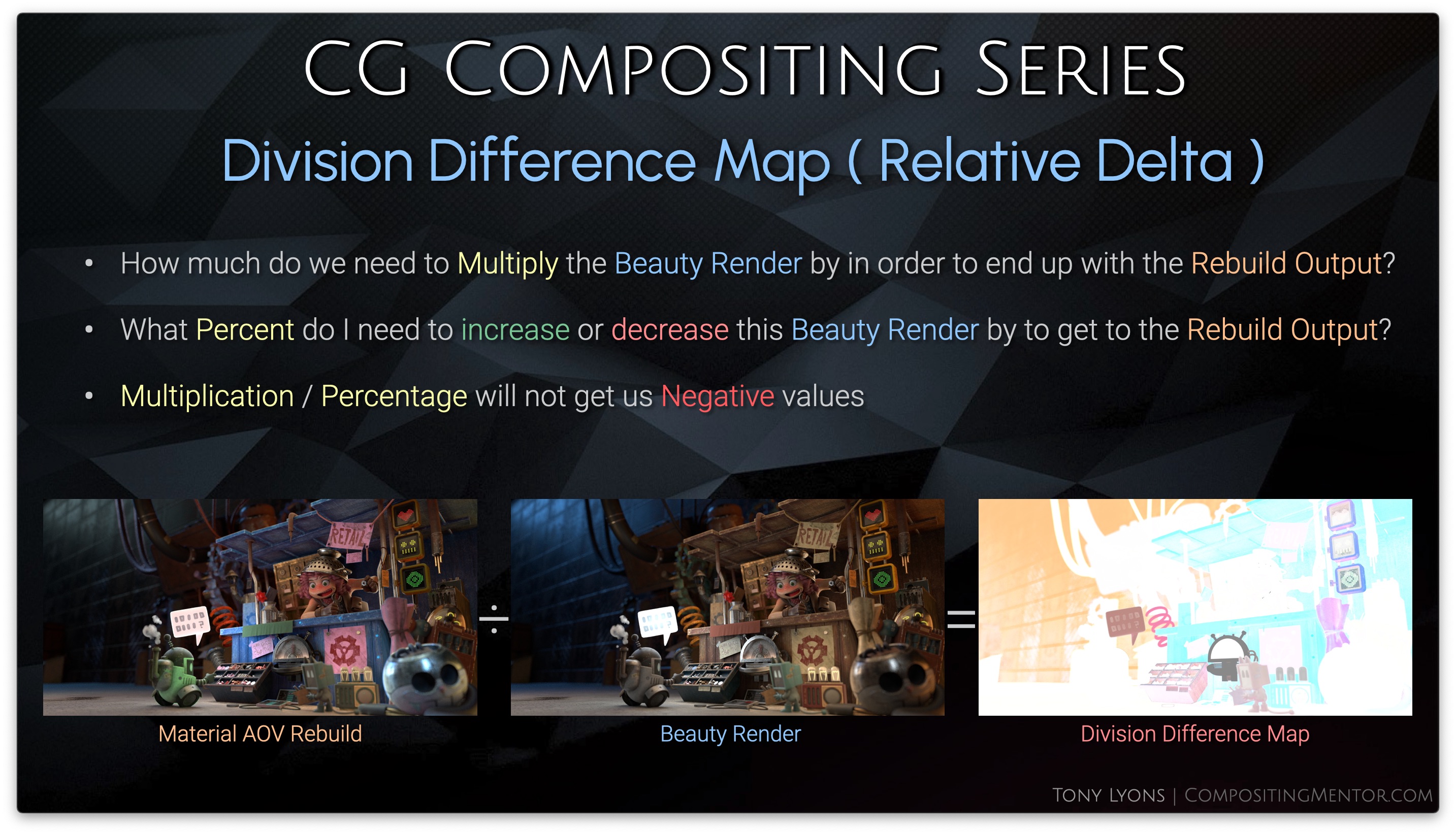
This new Difference map is answering a different question than the subtraction difference map was:
- How much do we need to Multiply the Beauty Render by in order to end up with the Rebuild Output?
- What Percent do I need to increase or decrease this Beauty Render by to get to the Rebuild Output
Multiplication / Percentage will not get us Negative values
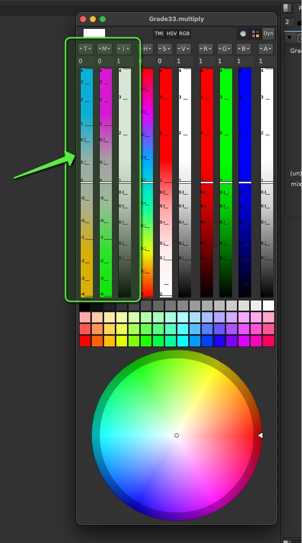
That Division Difference map appears all white, but in fact, it has values over 1, superwhites, that we cannot see by default. let’s darken it a bit so we can see the pixels over the value of 1.

Let’s break it down:
- Values above 1 will get brighter
- Values between 0 and 1 will get darker
- Value of 1 means No Change
So any number multiplied by 1, is itself, and does not change. That is why the map is mostly white.

Multiplication can also be represented as a percentage:

So we could express the pixels on this map in a percentage:

So our new map will be increasing or decreasing our 2nd Rebuild input by a specific percent.
Let’s go over the math equation to see how it works. Once again we have our inverse operation, Starting and returning to Material AOVs using division and multiplication:

Then we are swapping out the Beauty Render, in the second step, with our LightGroup output. So we are applying our Division Difference Changes on top of the LightGroup Changes.
It’s worth mentioning again, that just like before, it does not matter which order you divide or multiply the Rebuilds, Material AOV 1st & LightGroup 2nd or LightGroup 1st & Material AOV 2nd, will yield the same result.

So why does the Division Difference work so much better than the Subtractive Difference?
Below is a animation showing the difference between the add/subtract and multiply / percentage.
Notice that the subtraction will go past zero towards negative values, while multiplication will only approach zero or be zero, but never go negative. We don’t really ever see a negative percent.
Going back to that embedded layers image. This time, instead of subtracting the pass on both sides, we are multiplying to zero on both sides, but we don’t run into negatives, because if you multiply something by zero twice, it is still only zero. 4 x 0 x 0 = 0. So we are actually still safe.
I encourage you to stress test this Division Difference Method with your own renders and unique cases. You are able to push the limits to an extreme level without noticing anything breaking or feeling off.

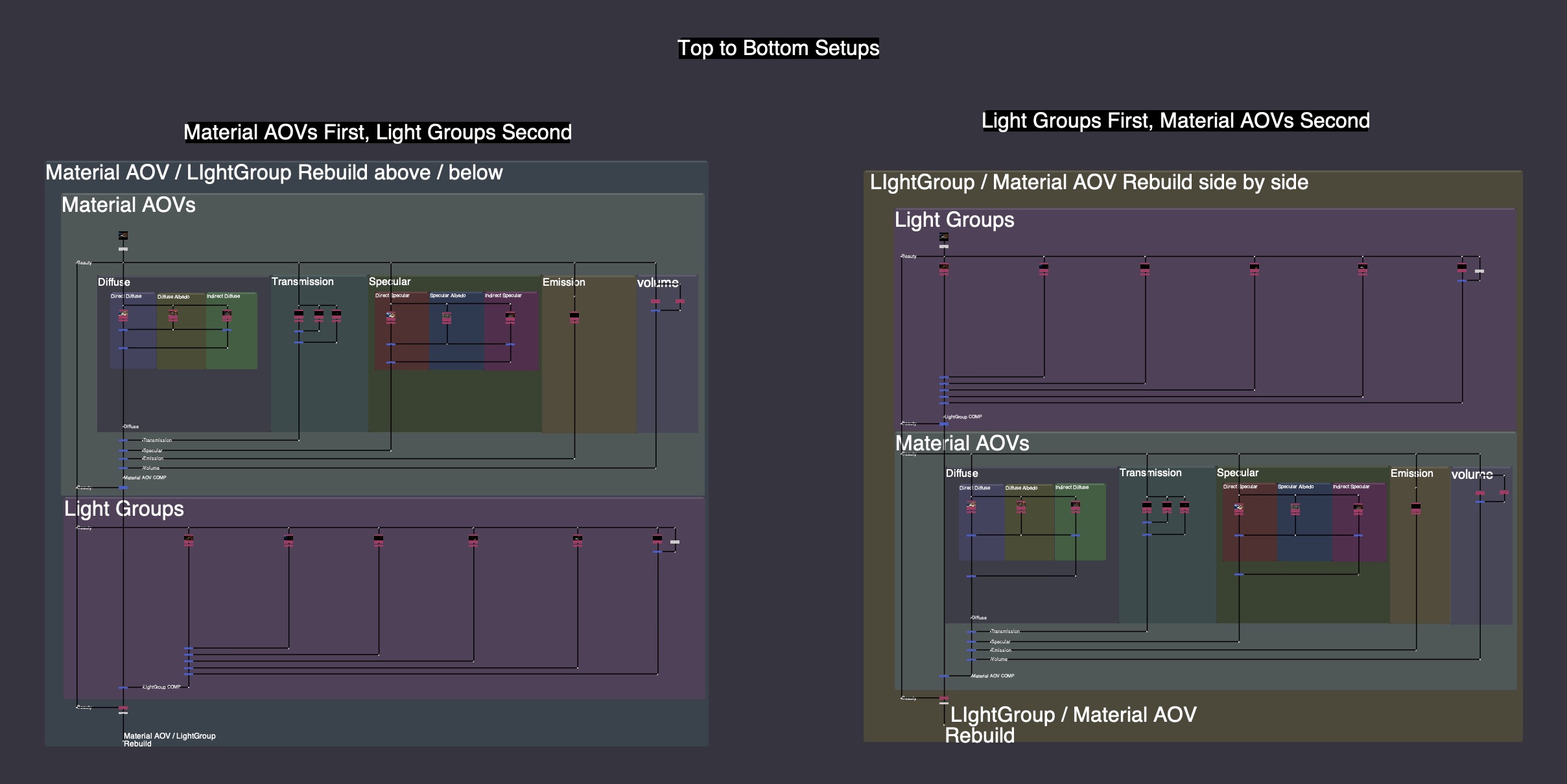
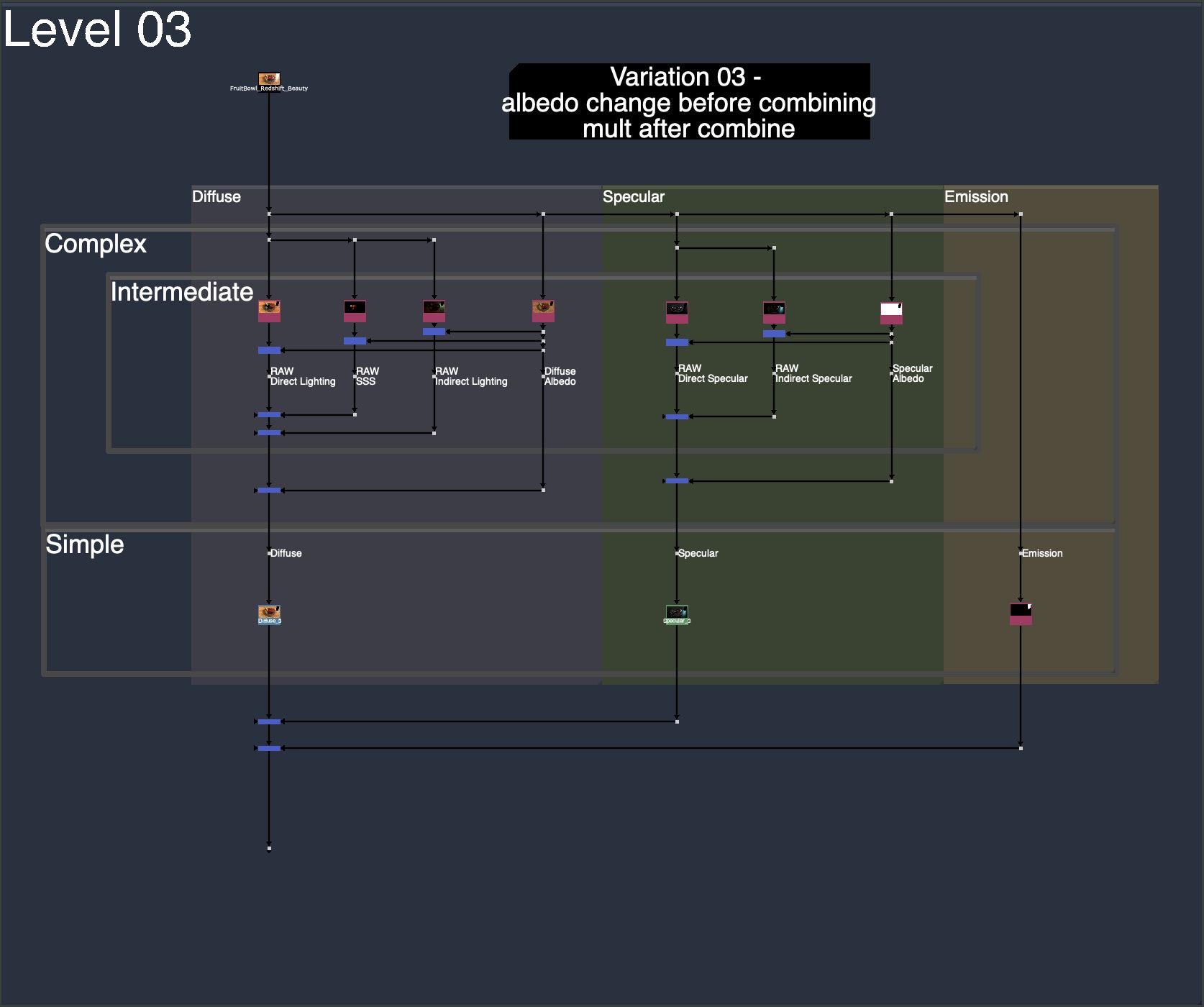
Template Layout Options
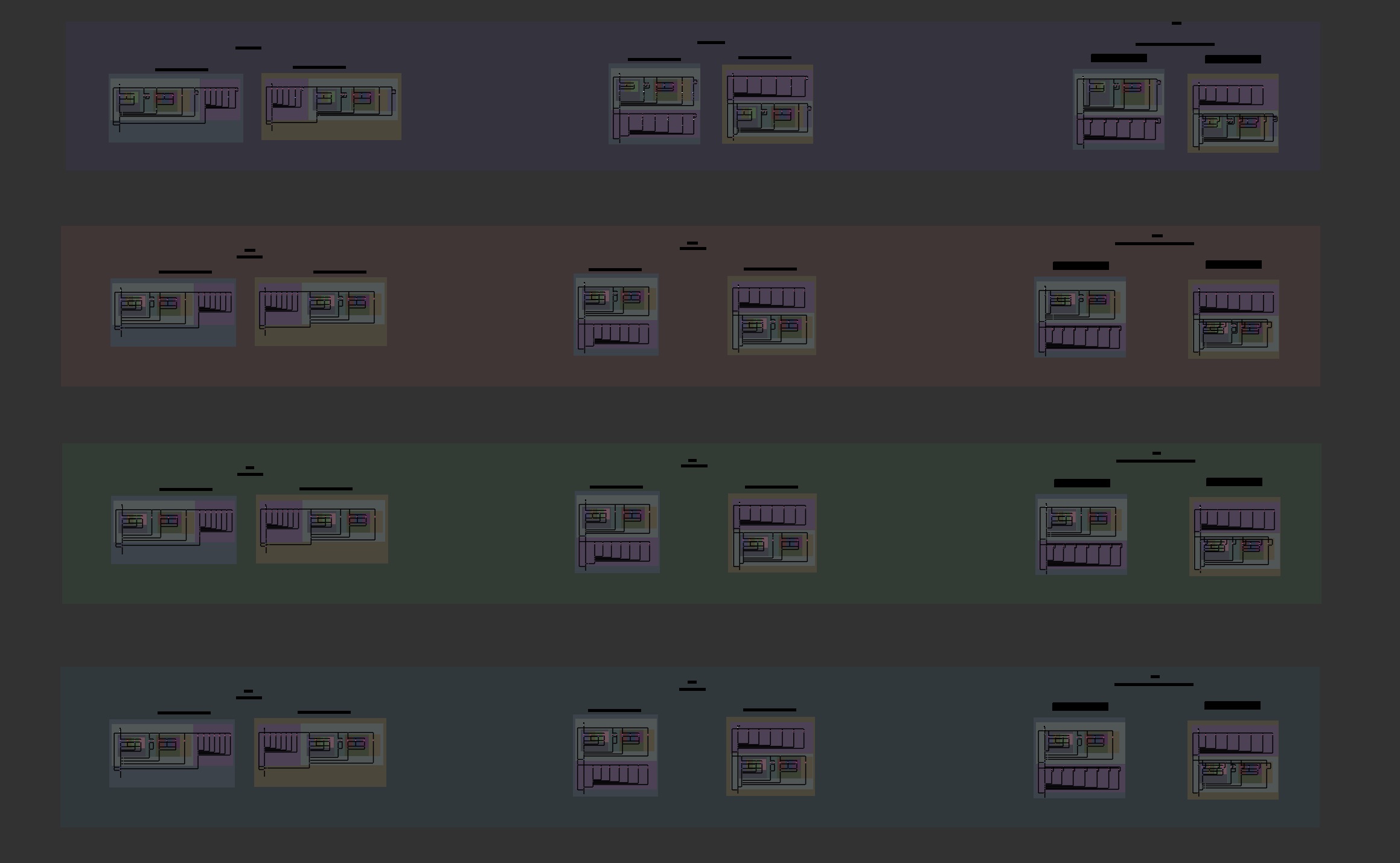
We have to decide if we want to set up our template with our 2 Rebuilds:
- side by side
- top to bottom
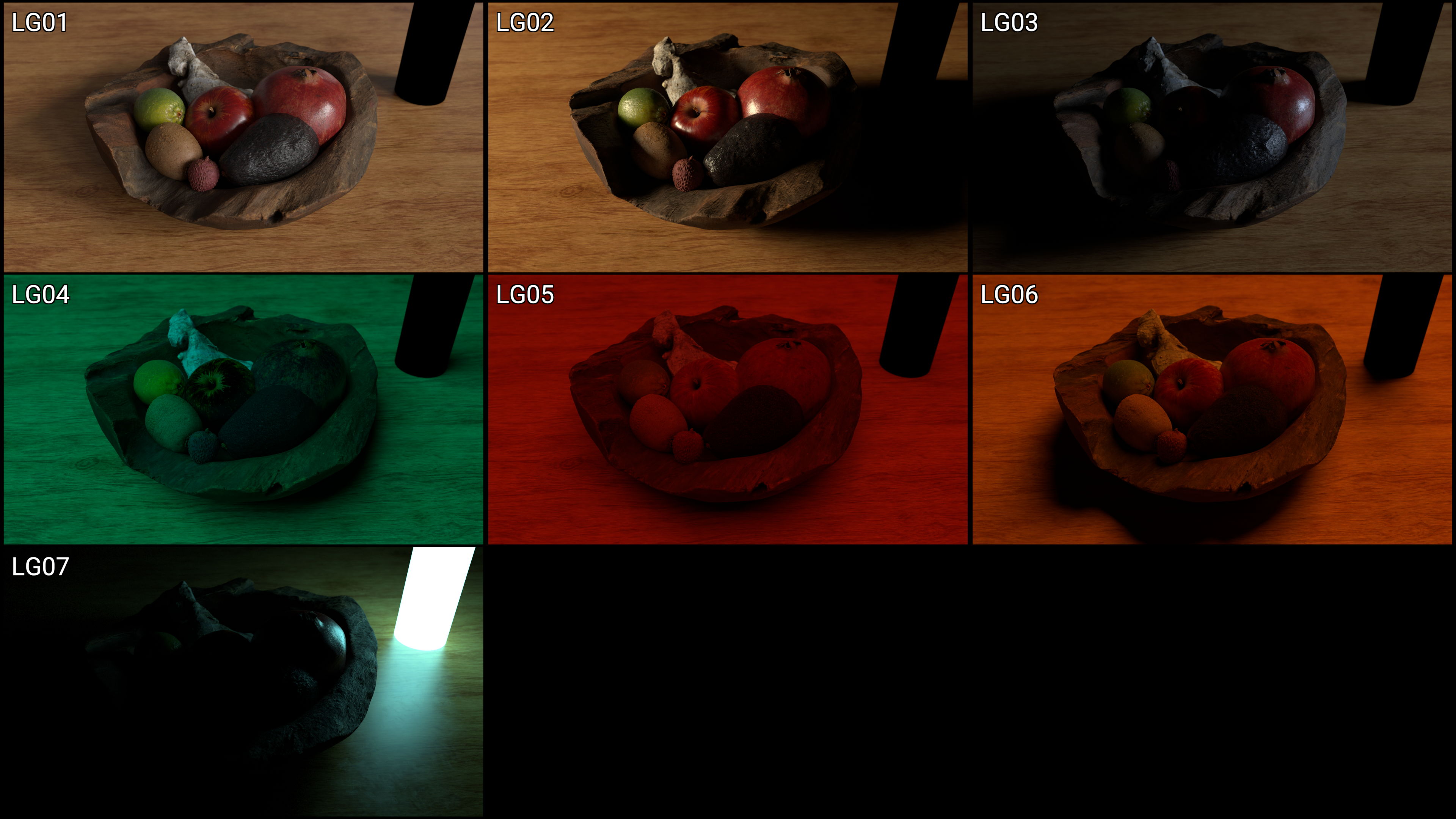
We also need to decide which Rebuild will be first and which will be second, the first will be the one captured in the change map. So either Material AOVs or LightGroups.


We could also go right to left instead of left to right, on the side by side, if we so choose:

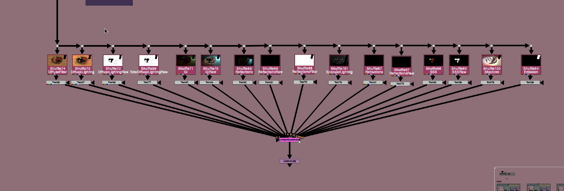
Here are some possible template layouts in the node graph:

One thing that is a bit annoying is that while using these Templates, and making changes, we can really only see the effect of our changes by looking at the very bottom, after the changes are combined and both setups are taken into consideration. Is there any way for us to have a more interactive experience, by seeing some of the changes affecting different parts of the Template. Let’s explore that idea.
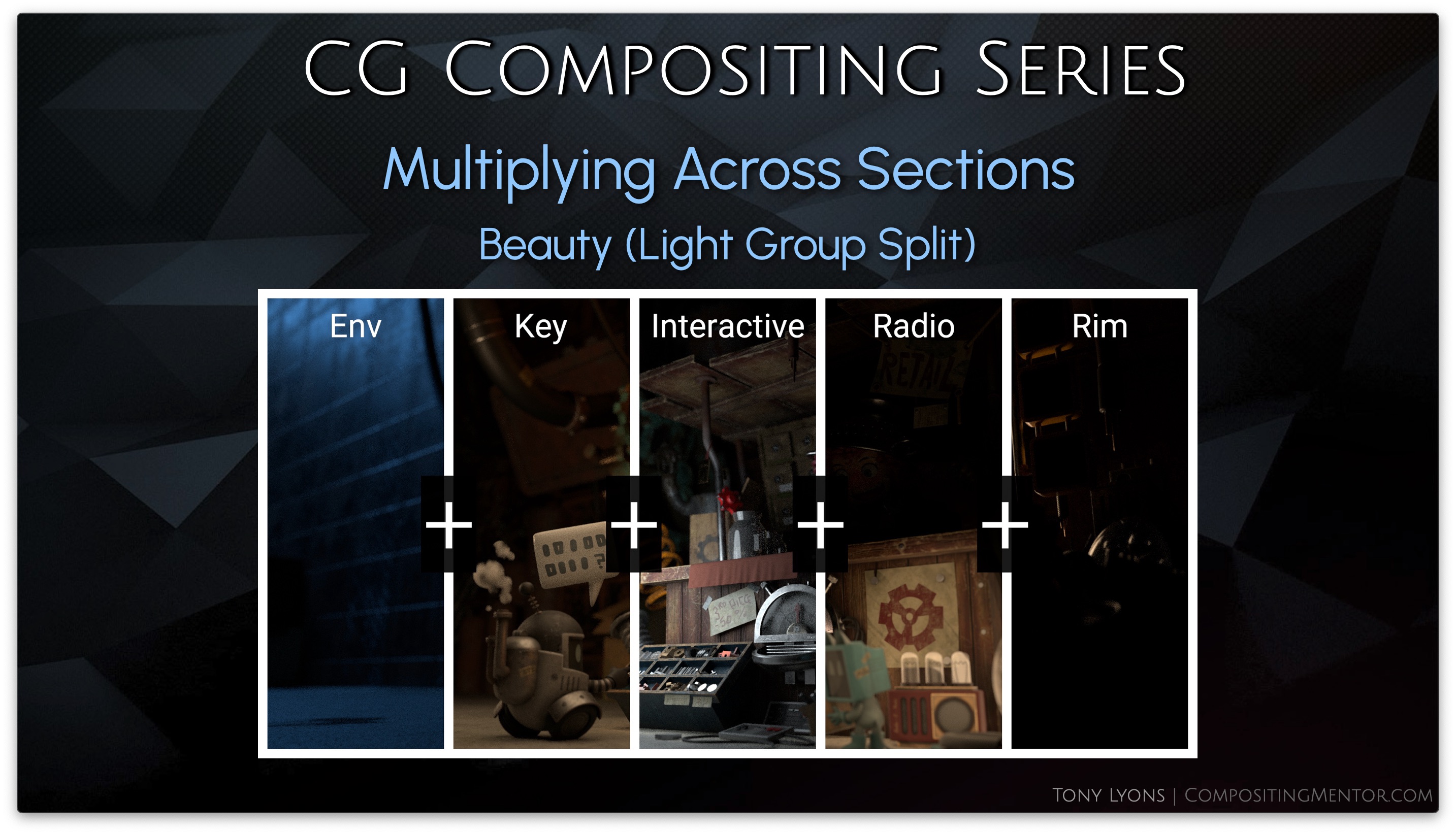
Interactive Changes throughout the Template
Instead of considering the Rebuild as 1 whole output, like our Beauty, we need to remember that it is made up of individual pieces, like our piechart from before. The passes were split and adjusted and added all up to equal the Beauty.

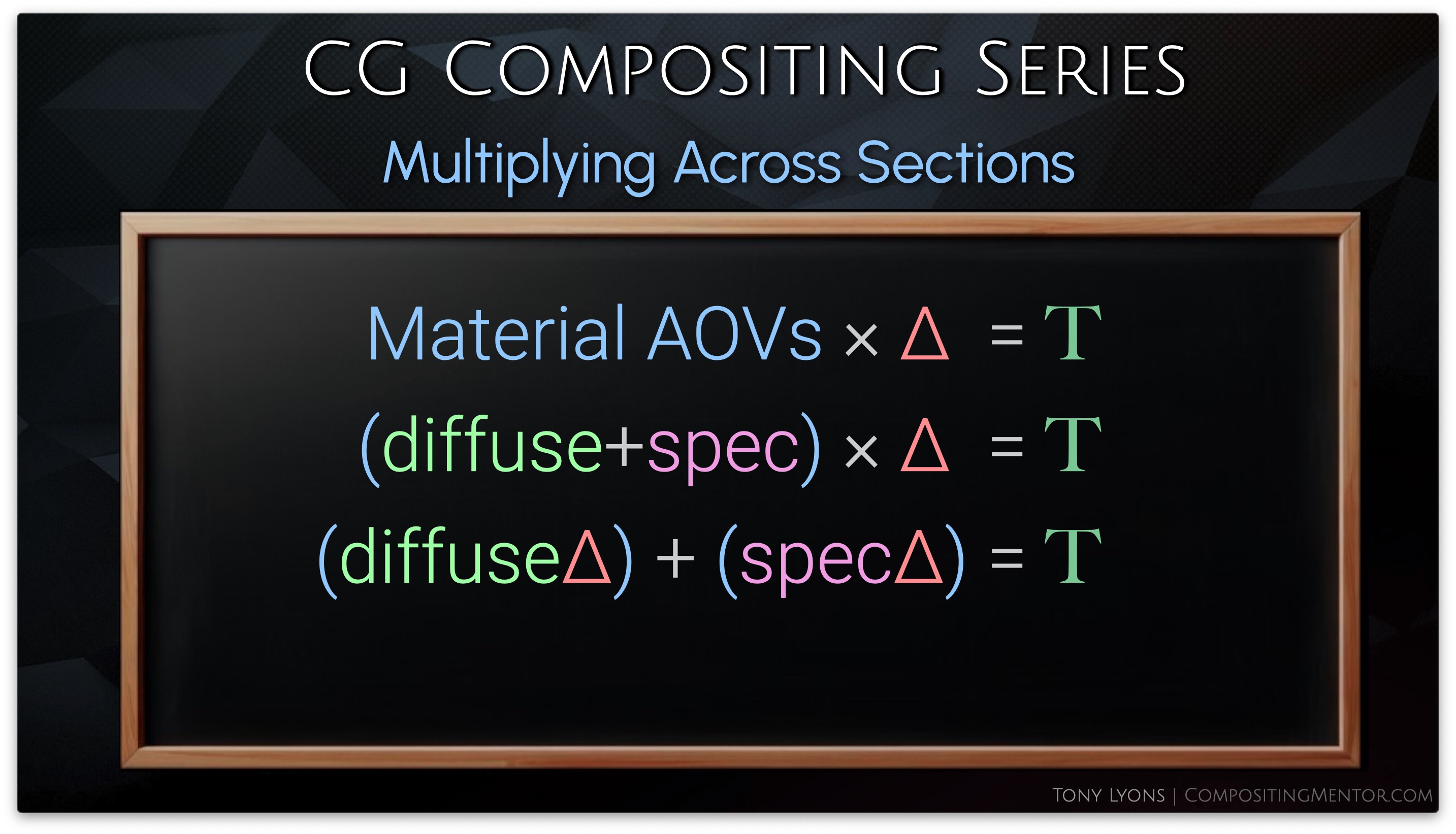
So instead of multiplying the Division Difference Change Map to the output of the 2nd Rebuild, we could multiply it to each individual pass separately. This would give us the same result once we add all the passes together.
Let’s explore the math of this, it becomes a little easier to understand.
If we split the Output into smaller components, we can apply the multiply to each component and then add them up after. This would be the same result as us just multiplying the whole.

The Equation for use would look something like this (Delta being the Difference, and T being Total Changes):
In nuke, we can set this up in our templates. I am just going to stick to Top to Bottom Templates for the example, as it’s a little easier to set up and understand.

It’s SUPER IMPORTANT to realize that we are only capturing the changes from the 1st setup, and applying them to the 2nd setup. There is no way to make the changes of the 2nd look back around and apply to the first, because you would create a paradoxical change loop: Changing the 1st, which changes the 2nd, which changes the 1st, which changes the 2nd, which changes the 1st…. you get the idea.
So that decision of the flow of your Template, and which setup you want to see the changes reflected in, is very important to decide as you build your CG Template
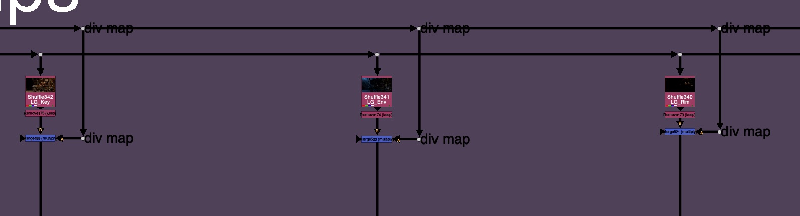
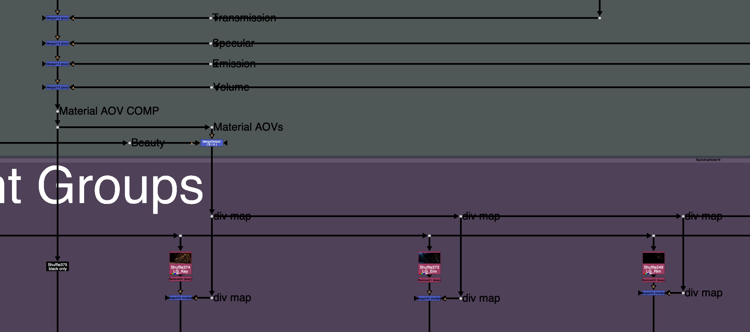
So, let’s say that we have our Material AOVs 1st, and we are applying the changes to the LightGroups. We’ll need to multiply each lightgroup pass with the division map
And if we started with LightGroups, we’d need to multiply the 2nd setup Material AOVs with the division difference map.

or if you were to use the LightGroups first, you could transfer your changes to each individual Material AOV:


The result is an interactive user experience where you we can see our changes trickle down throughout our template and influence all the downstream passes. This can really help visualize what is happening at a local level.
Rules and Caveats

- Material AOVs passes must add up to equal Beauty
- Light Groups passes must also add up to equal Beauty
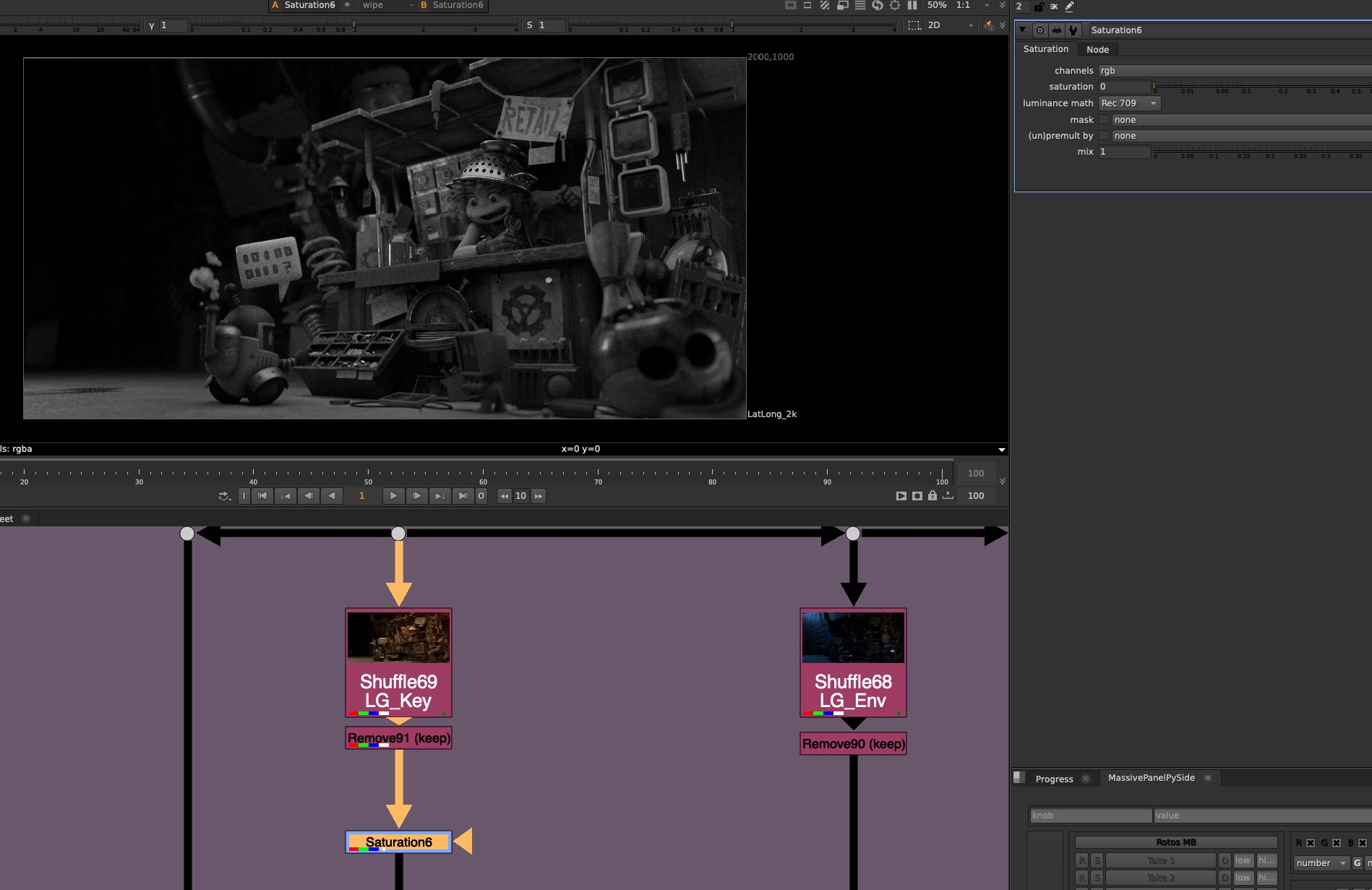
- Do not do color corrections that introduce negative values (saturation)
- Treat the CG Template as a glorified Color Correction

- On the 1st Rebuild side (The Captured Change side) avoid:
- Transforms / Warps
- Filters: Blur, Defocus, Median, Glow
- Chromatic Aberration
- Replacing / Merging a totally different image on top
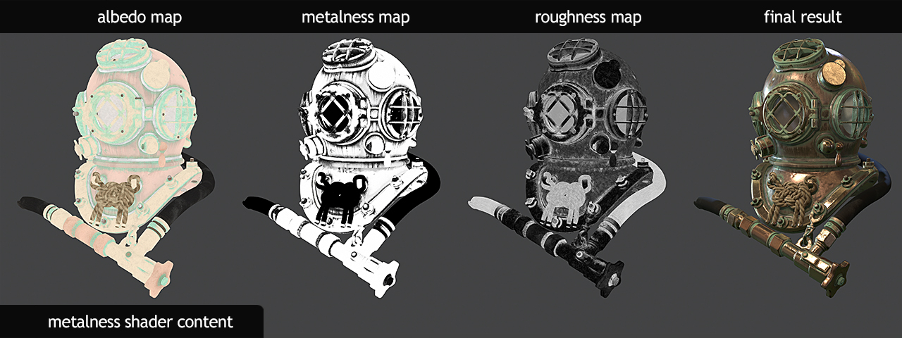
- Texture changes should happen at the albedo level
You want to try and consider the entire CG Template as one big color correction. The pixel is being tracked all the way through the setup, in the change map, and comparing back to the beauty and applying to the second rebuild. Things like Transforms or filters, are changing the possible, or blending pixels together, and will cause artifacting because the Change map is not able to really capture the changes properly. Also some filters are a post effect, and really should not be adjusted after use, such as a Glow.
Example of Glowing 1st rebuild and viewing result in 2nd rebuild:
Transforms or moving pixels around, will also not allow the setup to track the pixel the whole way through and leave to various artifacting, as shown below:
You will want to apply your filters and transforms either after the CG Template, or possible only on the 2nd Rebuild section. So basically avoiding the division change map, which is unable to capture it, and only applying those operations afterwards.
Template Examples
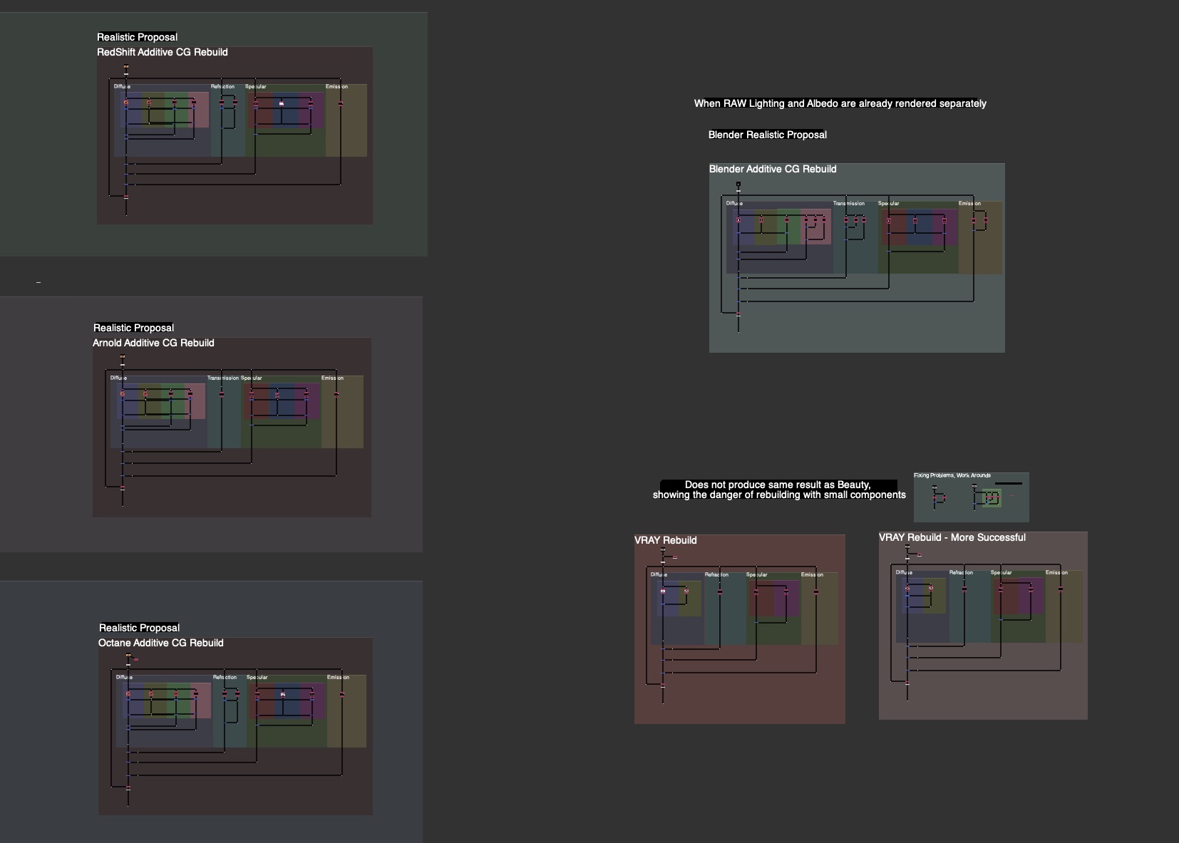
I will be providing you examples of Side by Side, Top to Bottom, and Interactive Change Templates for each renderer: Blender, RedShift, Arnold, and Octane.

Template Ideas and Inspiration
There are just way too many variations for me to provide in every situation. However I can give some example ideas or inspirations that I have seen and worked with that you could consider implementing into your CG Template if it fits with your style of comping.

- Managing Div-Map with Exposed Pipes
- Using Stamps or Hidden inputs for Div-Map

- Storing Div-Map in a Layer / Channel for later use

- Grouping Sections for less clutter


- Template Controller, pick which parts are in use:
- Beauty
- Material AOVs Only
- LightGroups Only
- Combined LG / AOV

- Reversed Direction

Conclusion
This Division Difference Multiplication Technique used to solve the LightGroup / AOV Paradox is fairly unknown at the moment. There seemed to be a huge black hole of knowledge out there on this subject. I’d like to give a huge shout out to Ernest Dios for being one of the true masterminds behind this technique, and for first introducing me to it. Also a big thank you to Alexey Kuchinski for all of his mentorship.
My hope with this whole CG Compositing Series was to equip you with the knowledge of every piece of the CG Template. What all the passes are, Why they are important, How to use them, Where to put them and how to organize them to Rebuild the Beauty, and When to adjust them for specific notes.
And of course, the final piece of the puzzle. How to combine it all and use the LightGroups and Material AOVs together in an elegant way. To help you push your CG Renders to their absolute limits, without the need for a rerender.
I hope you got value out of this video, or out of any video in the CG Compositing Series.
If I could ask one small favor from you, it would be to help share this video, or this blog, to compositing or VFX friends and colleagues. Whether it’s in a group chat, work chat, discord, linkedin post, I believe this knowledge is too important to keep secret. I would love to see this amazing workflow become more commonplace in the world of Compositing.
Thank you so much for all of your support over the years. It’s be a long journey since the first CG Compositing Series Intro video, and we are finally at the end…for now. I hope it was worth the wait.
Until next time.
Downloads
Nuke scripts
1 Demo nk script, and 1 Template & Idea Proposal nk script, 2 total:
CG_Comp_Series_4_1_LG_AOV_Paradox_Demo_Scripts.zip ( 164 kb )
Tools
MergeDivide tool that was demoed:

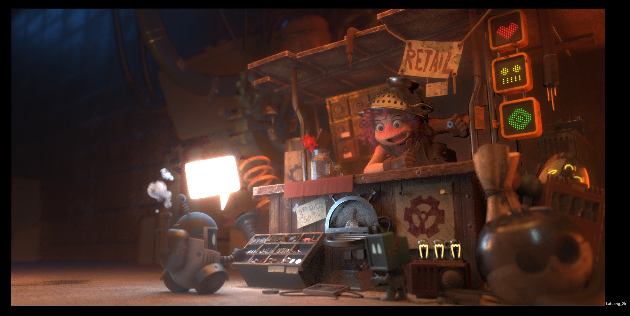
Junkyard

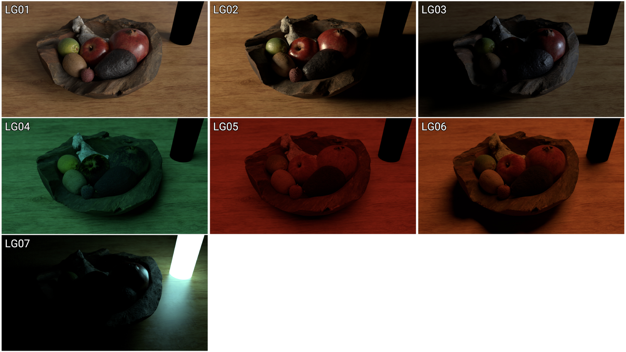
I’ve created a new Junkyard Render specifically for this Light Groups video, please download the Render and the Cryptomatte file here in order to relink it in the Demo nuke script:
Download Render files here:
Junkyard_LightGroups.zip ( 115 mb )
Junkyard_LightGroup_AOV_Split.exr ( 223 mb )
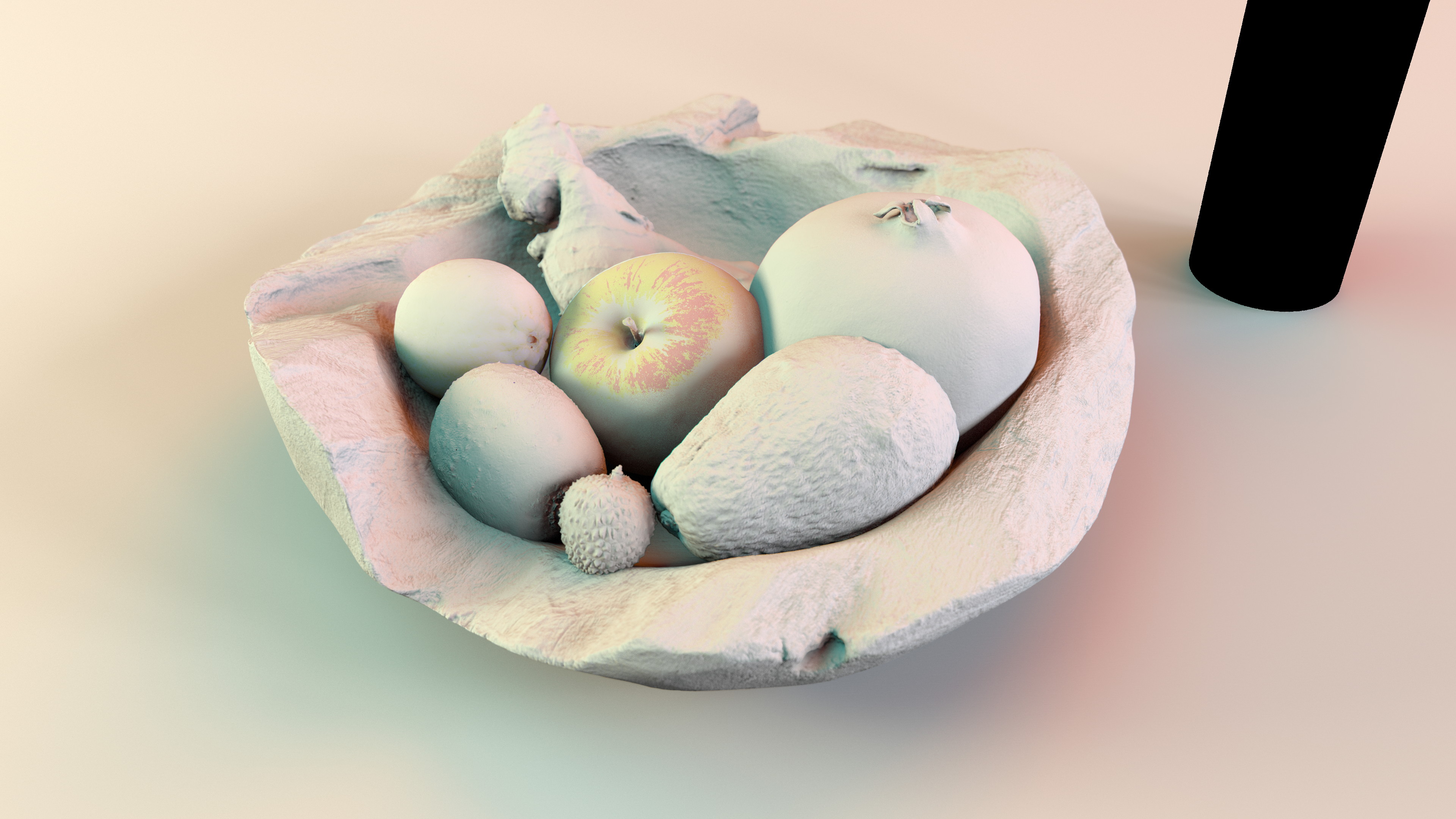
Fruitbowl
If you haven’t downloaded the FruitBowl Renders already yet, you can do so now:

You can Choose to either download all 3 FruitBowls at once:
FruitBowl_All_Renders_Redshift_Arnold_Octane.zip (1.61 GB)
Or Each FruitBowl Render Individually for faster downloads:
FruitBowl_Redshift_Render.zip (569.1 MB)
FruitBowl_Arnold_Render.zip (562.8 MB)
FruitBowl_Octane_Render.zip (515.4 MB)
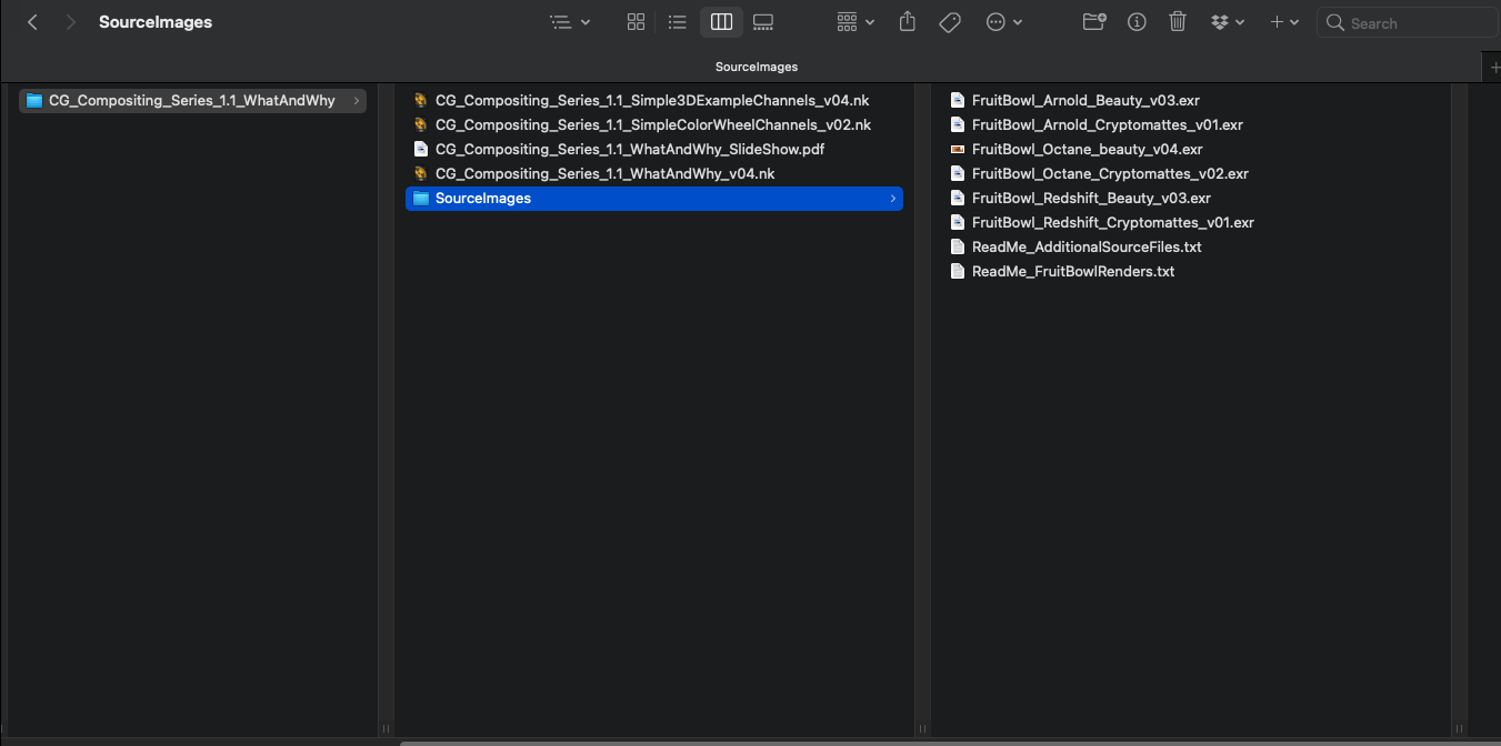
The project files and the Renders are separate downloads, so if you have already downloaded 1.1 What and Why files or the Fruitbowl Renders, there are a couple ways to combine them to work.
- Either add the .nk script to the previous package (in the folder above SourceImages, with the other .nk scripts)
- Or simply drop the Render files into the SourceImages folder of the project folder


